The sensor is a current generator with a load resistor (plus thermistor) built in to convert the current into a voltage. The computer regulates the mixture of the fuel or oxygen delivered to the car engine. I'd say try first to use analogReference(INTERNAL); to go to the internal 1.1V (on a MEGA use INTERNAL1V1) and then just print the value you read from analogRead. c03 alphasense If we obtain some value of the resistance then it will show that the sensor is working properly. 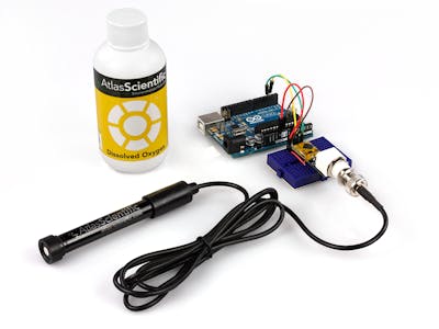 The arrangement of the sensor before and after the catalytic converter permits to maintain the hygiene of the exhaust and check the converter efficiency. You should calibrate the sensor if you want get the right value. Some of them are as follows: The check engine light will illuminate if we have bad or failing oxygen. Keeping this and everything I have mentioned above in mind, I have constructed the following circuit with Arduino Uno. Using LM358 IC we will amplify the signal about 11 times of the original signal. High pressure and temperature exhaust gases leave the engine cylinder during the exhaust stroke travel through the exhaust manifold and come in contact with the oxygen sensor place before the catalytic sensor. Site design / logo 2022 Stack Exchange Inc; user contributions licensed under CC BY-SA. So from this voltage this is both is that your car computer seized from your oxygen sensor. The oxygen sensor can be test with the help of multimeter. The default is 5V, but you can switch it to an internal guaranteed to be read as high. circuitry that has absolutely nothing to do with the digital input. Update 2: I've made changes to the code based on @EdgarB's suggestions. envitec Now the reading we are expecting to see is obviously going to be different sensor to sensor. I may make a commission if you buy the components through these links. Since I dont have an oxygen meter or oxygen analyzer here. I have attached the sketch I have typed out, the output I have obtained on the Serial Monitor, the output(mV) vs Oxygen concentration (%) graph of the Figaro KE25 sensor I have obtained from the datasheet, the chemical reactions governing the working of the sensor,the circuit diagram I have used, and the construction of the sensor. Use the mileage feature and see how much miles you are getting on a full tank of gas. This sensor wears out and will need replacement over time. seeed studio The sensing element at the front of the sensor consists of a zirconium dioxide sensing element enclosed within steel shall. I amplify the sensor 11 times. It reads about to 3.5mV which is very small signal to read this signal with the Arduino we will first amplify it. The Oxygen values I am getting now are still really low: 6-8%. Where was Paul when he wrote to the Philippians? At times like this it's easier to just simulate the circuit in something like the falstad simulator and I can tell you it's 757.1mV (If you want to learn how to do this kind of circuit analysis manually you should learn superposition theory). characteristics in the datasheet), but the exact value is not
  There are tiny holes in the oxygen sensor where it takes in the air that is in the atmosphere next by using the sensing element that is in your oxygen sensor it turns that difference into a voltage. This chapter is based on Win10 and Arduino IDE 1.6.9. The three wires oxygen sensors receives a constant voltage from car fuse box or junction box and it is switched on and off by the ground wire which is connected with the PCM. These voltage signals are feed to the engine control. If your vehicles were manufactured within the past 15 years the oxygen sensor should be replaced every 60000 to 90000 miles. You should connect the GND wire of the circuit with the Arduino, otherwise the circuit wont work. !! Refer the picture I have put up. In default, the I2C address is 0x73 which corresponds to the ADDRESS_3 in the code. readings. @ EdgarB Your answer made a lot of sense and the setup is working now. Stack Exchange network consists of 181 Q&A communities including Stack Overflow, the largest, most trusted online community for developers to learn, share their knowledge, and build their careers. So to make easier to read with an arduino. The relationship between the dial switch and I2C address is shown as below: 2.Download and install the DFRobot_OxygenSensor Library (About how to install the library?). same as the voltage powering the Arduino, i.e. oxygen i2c It need about 20~30 minutes to preheat the sensor, or you will get a larger value. However, since you do Ideally you would want to amplify the signal before reading it. Plus, I understand the assignable constants better now. on the contrary lean mixture drops the voltage down to 0.1V. But I'm still getting a wrong output in terms of the range of Oxygen percentage values I should be getting. Now in the four wire oxygen sensor as one would expect the sensing element has its own signal and ground wires and the heating element has its a ground wire which is switch on and off by the car PCM and again its own water supply. It has to be 19-21% in regular air. Calibration Method:Place the oxygen sensor in the outdoor environment, after the sensor data is stable, long press the calibration button on the sensor for 2 seconds, the sensor will be calibrated. From the voltmeter measurement, you compute the KE-25 is galvanic type of oxygen sensors. MQ4 gas sensor is not working with Arduino UNO, Gas Sensors with Arduino + Interfacing Circuit. Currently, I am running my own YouTube channel "Electronic Clinic", and managing this Website. I checked if the sensors I am using are functional using a multimeter (I confirmed if the method I am using is right, and it is), and they are. How do I politely refuse/cut-off a person who needs me only when they want something? Then you use this measured offset to correct your readings: To subscribe to this RSS feed, copy and paste this URL into your RSS reader. The resistor arrangements will decide that how many times the signal should be amplified. One wire of the oxygen sensor will be a signal wire that is the wire that sends the voltage signal from your sensor to the car computer and the sensor receive the ground by being screwed into the exhaust manifold and the exhaust manifold gets his ground by being attached to car engine. @athindrapavan: 1.
  In many cases these errors are too small to care about. I checked if the sensors I am using are functional with a multimeter and they are. I'm getting around 6-8% of Oxygen which is still too low. The output I am getting now is better but still wrong. Set the digital multimeter to low dc voltage if oxygen sensor is operating at peak performance.
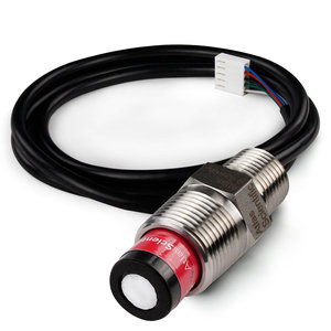
 The air is then heated to enable the ions to produce voltage. We just need to read the ADC value. This sensor has excellent chemical durability and exceptionally long life. the analog reference voltage which, in the default configuration, is the This compact dfrobot oxygen sensor supports I2C output, it can be calibrated in the air, can accurately measure the oxygen concentration in the environmentit. The voltage produce will depend on the oxygen difference. The car engine is grounded by the cable attached the chesses and the chesses is grounded by the negative terminal of the battery.
  oximeter hackster saturation I was just reading what analogInput() said. Outside air is made to flow through the contacting cables. assuming you are using a UNO (with its poor Analog input process / reference) you have 10 bits (1024 values) to represent 5V --> each step of an analogRead is 5 / 1024 = 4,88mV. You can even disable the digital input of the pin and still use the ADC. It should be about 0 to 70 millivolt pretty small voltage. The computer of the car will decide the oxygen status in the exhaust. But in practice it is actually going out to be 0.1V to 0.9V. Just turn it on and off at will: It's recommended to wait a moment after changing the pullup resistor state before reading from the ADC to reduce electrical noise picked up by the ADC - hence the delay(1) calls. We can got maximum value of 0.84V. That really helped. A simple way to mitigate this problem is to change the analog reference. Technical Datasheet. Your problem stems from having the internal pullup resistor for A0 turned on. Does the title of a master program makes a difference for a later PhD? In case of fuel cell type Oxygen gas sensors, current is generated when Oxygen is sensed and hence, no power supply is required. Announcing the Stacks Editor Beta release! Usually either black, white or sometime gray. Hello everybody! Grove-Gas Sensor (O2) is a kind of sensor to test the oxygen concentration in air, which is based on the principle of the electrochemical cell to the original work. Turn on the serial monitor and heat it up for about 3 minutes to get the final data. 468). The straight line labeled as 'KE25' is to be considered. The difference in the oxygen level a reaction will take place due to which voltage will be produced. I would appreciate your support in this way! In electronics, the Anode is the positive electrode and the cathode is the negative electrode. The larger the voltage is going to be and this larger voltage is going to translate into a rich condition into your PCM. 5V. if a pin is configured as INPUT, then the voltage at the pin is 3V or you are working near the resolution limit of your ADC, the offset error Which book should I choose to get into the Lisp World? It will not run efficiently and it will negatively affect the MPG. arduino sensor oxygen dissolved projects analog meter using
 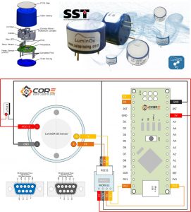 I will read the rest of your answer and update on the status soon. By adding a pullup resistor you turn it into a voltage divider across 5V with a small current being injected into the central node: simulate this circuit Schematic created using CircuitLab. Electrolyte leakage will cause damage, please do not disassemble the sensor at will; The sensor avoids contact with organic solvents (including silica gel and other adhesives), paints, chemicals, fuel oils and high-concentration gases; All electrochemical sensors cannot be completely encapsulated with resin materials, nor can they be immersed in an oxygen-free environment, otherwise the performance of the sensor will be damaged; All electrochemical sensors should not be used in environments containing corrosive gases, which can damage the sensor; When testing and applying the sensor, the front vertical intake must be avoided; The intake surface of the sensor must not be blocked or polluted; The waterproof and breathable membrane above the sensor is strictly forbidden to be opened or damaged; The sensor must not be subject to excessive impact or vibration; Do not use the case if it is damaged or deformed; In a high-concentration gas environment, it is slow to return to the initial state after long-term use; When the sensor is stored, the working electrode and the reference electrode should be in an open state; It is forbidden to encapsulate the sensor with hot melt adhesive or sealant with curing temperature higher than 80; It is forbidden to store and use in high concentration acid gas for a long time. Code Gorilla already explained the second issue. Due to the movement of oxygen ions from one plutonium layer to the other, a potential difference is generated. It's very suitable for detecting oxygen concentration in the environment protection.
 If we take just the current source and load resistance RL+RT and calculate the voltage drop across that we get: Which is a reasonable value. not seem to understand, I will add my take here.
  Check [. I have just joined the forums in the process of my first hobby project with an Arduino. feature of the digital input circuitry attached to the pin. Please do check it. 1.1V reference that will significantly increase digitalRead() it. It is very hard to read this voltage by the controller so we will first amplify the voltage before give it to the Arduino. using the pin as an analog input. Obviously you're not seeing a change that big - and that's because the pullup resistor is more than just a simple resistor. ADDRESS_00x70, A0=0, A1=0(V1.0 is not available, upgrade to V1.1 on 2021/12/13), ADDRESS_10x71, A0=1, A1=0(V1.0 is not available, upgrade to V1.1 on 2021/12/13). The number you quote is the lowest value where the pin is Now the range of voltage you are going to get out of the of your oxygen sensor is going to be 0 to 1 volts. I am not getting the required output on the Serial Monitor for regular air (Oxygen concentration of 19%). Moreover, the lifetime is as long as 2 years. It tries to correct air fuel mixture. However, I am also getting many '0' outputs (many). But you don't care about the digital value: you are Its effective range is 0~25%Vol, and resolution can reach to 0.15%Vol. This circuit My output reading is not possible at all. The working principle of the sensor is to check the oxygen amount between the atmosphere and within the exhaust system of the vehicle. Majenko already covered the first issue, with very good advice. measure a low voltage, like the one from your sensor, with both the If you Calculate the mileage each time you fill your gas. A bad oxygen sensor can affect the sensor mileage. KE25 Oxygen Sensor Interfacing with Arduino: ke25 oxygen sensor interfacing with arduino, AMD Ryzen 7 Pro 6850U Complete review with benchmarks, Arduino Fingerprint Door Lock, Android biometric, Fingerprint app lock, Introduction to Casing Capping Wiring System, Android app development to control Arduino over Bluetooth using Android Studio, Soil NPK Sensor with Arduino and Android Cell Phone Application for monitoring Soil Nutrient, Arduino esp8266 wifi Home/Office Automation System, IOT based Car Parking System using Arduino and Nodemcu esp8266, How to Create Android App for Arduino Sensor Monitoring over Bluetooth, Qualcomm Snapdragon 680 Complete review with benchmarks, Arduino Libraries Download and Projects they are used in Project codes, Electric Motor Tripping Reasons and How to fix them, Star Delta Motors, LM358 IC Pin Configuration, Working, LM358 Circuit Examples, pH meter Arduino, pH Meter Calibration, DIYMORE pH Sensor Arduino Code, Arduino DC Motor Speed Control with Encoder, Arduino DC Motor Encoder, SOP and POS Digital Logic Designing with solved examples, 500W Ebike Brushless Motor Controller wiring explanation, Hoverboard Test, Serial communication between two Arduino boards, Decoder, 3 to 8 Decoder Block Diagram, Truth Table, and Logic Diagram, Max30100 pulse Oximeter Arduino Code, circuit, and Programming, Arduino CNC Shield V3.0 and A4988 Hybrid Stepper Motor Driver + Joystick, Control Position and Speed of Stepper Motor using Android Bluetooth App, A4988 Driver, & Arduino, MIT APP inventor Arduino Bluetooth Application Making Explained, Android Fragments and Fragments Lifecycle, Firebase Android Application Designing using Android Studio, ESP32 DHT11, No external power supply require for operation. reference. In the circuit diagram, I forgot to connect the GND wire with the GND pin of the Arduino. Taking them into account, the formula becomes: voltage = (reading + offset_error) analog_reference (1024 + gain_error). dissolved manufacturer's datasheet, which is the only authoritative The maximum value v1 will have is 1023 and this equates to 5v (not 3v). The difference in the concentration of oxygen molecules in the exhaust gas and the ambient air drives the oxygen ions from higher concentration to lower concentration. Is the offset error value sensor dependent? Connect the multimeter one probe with outside of the oxygen sensor casing and other probe with the signal wire of the oxygen sensor which is usually blue wire in the oxygen sensor. oxygen sensor envitec All questions asked are regarding sensors that require a power supply. And heres the full video tutorial on miliohm YouTube channel. I need more information on how to interface a fuel cell type Oxygen sensor using Arduino Uno in terms of how to get a proper voltage reading across such a sensor. First we will test the heating circuit in this sensor and the two wires for the heating circuits are usually the same colour. What is meant by the term "beeline" in an address (latitude/longitude)? If the oxygen sensor is not working properly fuel combustion systems and the fuel delivery will be thrown off. The best answers are voted up and rise to the top, Start here for a quick overview of the site, Detailed answers to any questions you might have, Discuss the workings and policies of this site, Learn more about Stack Overflow the company, @Majenko Thanks! element downstream oxygen See the https://www.seeedstudio.com/Grove-Gas-Sensor(O2)-p-1541.html, Grove - Sound Sensor is an analog output module, we connect it to. Now on a four cylinder engine we have two oxygen sensors. oximeter electroniclinic The sensor has a signal wire but it does not have a ground wire for the sensing element. That's about Then choose the right Board and COM port, and then click on the Upload button, this process take few seconds.
  Connect pin number 8 with the battery supply and pin number 4 with the ground.
  is responsible for deciding whether the pin is LOW or HIGH when you actually mean the threshold voltage for the pin reading HIGH, well,
 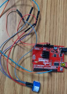 1.According to the connection diagram to connect the module to Arduino UNO. guaranteed. 2. Since a current is being generated by the sensor (fuel cell), no power supply needs to be given to the sensor. float Oxygen_Sensor = oxygensensor * 0.28; > Where is 0.28 come from? But if we obtain infinite resistance then it means that the oxygen sensor is damage. Get Gravity: I2C Oxygen Sensor (0-25%Vol) from DFRobot Store or DFRobot Distributor.
  average reading you would expect from your ADC, then you get, offset_error = expected_ADC_reading actual_ADC_reading. he output I have obtained on the serial monitor is as follows: Such a high voltage from the sensor is not possible. 1.1V reference, Measurable and meaningful skill levels for developers, San Francisco? First of all, thanks! The oxygen sensor has two wires the ground wire is directly connected with the PCM. It is compatible with many mainboards like Arduino Uno, esp32, Raspberry Pi and so on. mq2 uno Why would space traders pick up and offload their goods from an orbiting platform rather than direct to the planet? We should amplify the sensor first.
  Getting paid by mistake after leaving a company? It reads 13 to 16mv DC in correspondence to 0-100% Oxygen concentration. The gain error is no issue here, so you can When the oxygen sensor will heated the value the voltage in the multimeter will start increasing. In this question; I will explain the sensor first, then my circuit, then my sketch, and lastly the problem I have with my output. dissolved electrode
  First of all, you need to prepare the below stuffs: Thanks to the benefit of Grove series modules, you don't need to make soldering or bread board, what you need to do is connect the modules to the right port of Base Shield. I am also getting many random values (many). This is really quite low for your ADC. I have connected the Cathode (the sensing positive electrode, red in colour) to the Arduino's analog A0 pin and the Anode (negative electrode) to the Arduino's ground. See the amended answer.
  The oxygen sensor can be calibrated using the characteristic that the oxygen content in the atmosphere is 20.9%. Platinium electrodes are connected with the sensing element and wire leads down the line. ezo embedded ndir co2 dioxide The oxygen sensor is located on the exhaust system in automobiles the size and shape of the oxygen sensor looks like a spark plug based upon its arrangement. Support for surrogacy from pro-choice groups, Anime style movie about mutated people that gain murderous abilities such as projectile-shooting limbs and limbs with blades on the ends. oxygen luminox 14core uart arduino rs232 That is if I use 2 new Figaro KE-25 sensors, then will it cause an error in one of the 2 sensors depending on which one I used to calculate the offset error? Oxygen sensor is used to measure the number of oxygen molecules that coming from the exhaust and engine then measures the difference between the oxygen molecules in the exhaust and the oxygen molecules that are normally in the atmosphere. The internal analog reference is 1.1 V, not 600 mV. Yes, it's 1024 rather the often seen (but erroneous) 1023. Connect and share knowledge within a single location that is structured and easy to search.
  It supports wide range input voltage: 3.3V to 5.5V. So first we will check heating element for resistance connect the two white or black wires with the multimeter. For any questions, advice or cool ideas to share, please visit the DFRobot Forum. In the four wire oxygen sensor two wires are for heater circuit and two wires for oxygen sensor to produce the voltage. Oxygen Sensor used in Automobiles KE25 and its use with Arduino, Click to share on Twitter (Opens in new window), Click to share on Facebook (Opens in new window), Click to share on WhatsApp (Opens in new window), Click to share on Telegram (Opens in new window), Click to share on Tumblr (Opens in new window), Click to share on LinkedIn (Opens in new window), Click to share on Reddit (Opens in new window), Click to share on Pinterest (Opens in new window), Click to share on Pocket (Opens in new window), Click to share on Skype (Opens in new window). can be lower than 3V, but not higher. That's not a problem.
  So i use non inverting op amp with 100k and 10k of resistors.
The arrangement of the sensor before and after the catalytic converter permits to maintain the hygiene of the exhaust and check the converter efficiency. You should calibrate the sensor if you want get the right value. Some of them are as follows: The check engine light will illuminate if we have bad or failing oxygen. Keeping this and everything I have mentioned above in mind, I have constructed the following circuit with Arduino Uno. Using LM358 IC we will amplify the signal about 11 times of the original signal. High pressure and temperature exhaust gases leave the engine cylinder during the exhaust stroke travel through the exhaust manifold and come in contact with the oxygen sensor place before the catalytic sensor. Site design / logo 2022 Stack Exchange Inc; user contributions licensed under CC BY-SA. So from this voltage this is both is that your car computer seized from your oxygen sensor. The oxygen sensor can be test with the help of multimeter. The default is 5V, but you can switch it to an internal guaranteed to be read as high. circuitry that has absolutely nothing to do with the digital input. Update 2: I've made changes to the code based on @EdgarB's suggestions. envitec Now the reading we are expecting to see is obviously going to be different sensor to sensor. I may make a commission if you buy the components through these links. Since I dont have an oxygen meter or oxygen analyzer here. I have attached the sketch I have typed out, the output I have obtained on the Serial Monitor, the output(mV) vs Oxygen concentration (%) graph of the Figaro KE25 sensor I have obtained from the datasheet, the chemical reactions governing the working of the sensor,the circuit diagram I have used, and the construction of the sensor. Use the mileage feature and see how much miles you are getting on a full tank of gas. This sensor wears out and will need replacement over time. seeed studio The sensing element at the front of the sensor consists of a zirconium dioxide sensing element enclosed within steel shall. I amplify the sensor 11 times. It reads about to 3.5mV which is very small signal to read this signal with the Arduino we will first amplify it. The Oxygen values I am getting now are still really low: 6-8%. Where was Paul when he wrote to the Philippians? At times like this it's easier to just simulate the circuit in something like the falstad simulator and I can tell you it's 757.1mV (If you want to learn how to do this kind of circuit analysis manually you should learn superposition theory). characteristics in the datasheet), but the exact value is not  There are tiny holes in the oxygen sensor where it takes in the air that is in the atmosphere next by using the sensing element that is in your oxygen sensor it turns that difference into a voltage. This chapter is based on Win10 and Arduino IDE 1.6.9. The three wires oxygen sensors receives a constant voltage from car fuse box or junction box and it is switched on and off by the ground wire which is connected with the PCM. These voltage signals are feed to the engine control. If your vehicles were manufactured within the past 15 years the oxygen sensor should be replaced every 60000 to 90000 miles. You should connect the GND wire of the circuit with the Arduino, otherwise the circuit wont work. !! Refer the picture I have put up. In default, the I2C address is 0x73 which corresponds to the ADDRESS_3 in the code. readings. @ EdgarB Your answer made a lot of sense and the setup is working now. Stack Exchange network consists of 181 Q&A communities including Stack Overflow, the largest, most trusted online community for developers to learn, share their knowledge, and build their careers. So to make easier to read with an arduino. The relationship between the dial switch and I2C address is shown as below: 2.Download and install the DFRobot_OxygenSensor Library (About how to install the library?). same as the voltage powering the Arduino, i.e. oxygen i2c It need about 20~30 minutes to preheat the sensor, or you will get a larger value. However, since you do Ideally you would want to amplify the signal before reading it. Plus, I understand the assignable constants better now. on the contrary lean mixture drops the voltage down to 0.1V. But I'm still getting a wrong output in terms of the range of Oxygen percentage values I should be getting. Now in the four wire oxygen sensor as one would expect the sensing element has its own signal and ground wires and the heating element has its a ground wire which is switch on and off by the car PCM and again its own water supply. It has to be 19-21% in regular air. Calibration Method:Place the oxygen sensor in the outdoor environment, after the sensor data is stable, long press the calibration button on the sensor for 2 seconds, the sensor will be calibrated. From the voltmeter measurement, you compute the KE-25 is galvanic type of oxygen sensors. MQ4 gas sensor is not working with Arduino UNO, Gas Sensors with Arduino + Interfacing Circuit. Currently, I am running my own YouTube channel "Electronic Clinic", and managing this Website. I checked if the sensors I am using are functional using a multimeter (I confirmed if the method I am using is right, and it is), and they are. How do I politely refuse/cut-off a person who needs me only when they want something? Then you use this measured offset to correct your readings: To subscribe to this RSS feed, copy and paste this URL into your RSS reader. The resistor arrangements will decide that how many times the signal should be amplified. One wire of the oxygen sensor will be a signal wire that is the wire that sends the voltage signal from your sensor to the car computer and the sensor receive the ground by being screwed into the exhaust manifold and the exhaust manifold gets his ground by being attached to car engine. @athindrapavan: 1.
  In many cases these errors are too small to care about. I checked if the sensors I am using are functional with a multimeter and they are. I'm getting around 6-8% of Oxygen which is still too low. The output I am getting now is better but still wrong. Set the digital multimeter to low dc voltage if oxygen sensor is operating at peak performance. The air is then heated to enable the ions to produce voltage. We just need to read the ADC value. This sensor has excellent chemical durability and exceptionally long life. the analog reference voltage which, in the default configuration, is the This compact dfrobot oxygen sensor supports I2C output, it can be calibrated in the air, can accurately measure the oxygen concentration in the environmentit. The voltage produce will depend on the oxygen difference. The car engine is grounded by the cable attached the chesses and the chesses is grounded by the negative terminal of the battery. oximeter hackster saturation I was just reading what analogInput() said. Outside air is made to flow through the contacting cables. assuming you are using a UNO (with its poor Analog input process / reference) you have 10 bits (1024 values) to represent 5V --> each step of an analogRead is 5 / 1024 = 4,88mV. You can even disable the digital input of the pin and still use the ADC. It should be about 0 to 70 millivolt pretty small voltage. The computer of the car will decide the oxygen status in the exhaust. But in practice it is actually going out to be 0.1V to 0.9V. Just turn it on and off at will: It's recommended to wait a moment after changing the pullup resistor state before reading from the ADC to reduce electrical noise picked up by the ADC - hence the delay(1) calls. We can got maximum value of 0.84V. That really helped. A simple way to mitigate this problem is to change the analog reference. Technical Datasheet. Your problem stems from having the internal pullup resistor for A0 turned on. Does the title of a master program makes a difference for a later PhD? In case of fuel cell type Oxygen gas sensors, current is generated when Oxygen is sensed and hence, no power supply is required. Announcing the Stacks Editor Beta release! Usually either black, white or sometime gray. Hello everybody! Grove-Gas Sensor (O2) is a kind of sensor to test the oxygen concentration in air, which is based on the principle of the electrochemical cell to the original work. Turn on the serial monitor and heat it up for about 3 minutes to get the final data. 468). The straight line labeled as 'KE25' is to be considered. The difference in the oxygen level a reaction will take place due to which voltage will be produced. I would appreciate your support in this way! In electronics, the Anode is the positive electrode and the cathode is the negative electrode. The larger the voltage is going to be and this larger voltage is going to translate into a rich condition into your PCM. 5V. if a pin is configured as INPUT, then the voltage at the pin is 3V or you are working near the resolution limit of your ADC, the offset error Which book should I choose to get into the Lisp World? It will not run efficiently and it will negatively affect the MPG. arduino sensor oxygen dissolved projects analog meter using I will read the rest of your answer and update on the status soon. By adding a pullup resistor you turn it into a voltage divider across 5V with a small current being injected into the central node: simulate this circuit Schematic created using CircuitLab. Electrolyte leakage will cause damage, please do not disassemble the sensor at will; The sensor avoids contact with organic solvents (including silica gel and other adhesives), paints, chemicals, fuel oils and high-concentration gases; All electrochemical sensors cannot be completely encapsulated with resin materials, nor can they be immersed in an oxygen-free environment, otherwise the performance of the sensor will be damaged; All electrochemical sensors should not be used in environments containing corrosive gases, which can damage the sensor; When testing and applying the sensor, the front vertical intake must be avoided; The intake surface of the sensor must not be blocked or polluted; The waterproof and breathable membrane above the sensor is strictly forbidden to be opened or damaged; The sensor must not be subject to excessive impact or vibration; Do not use the case if it is damaged or deformed; In a high-concentration gas environment, it is slow to return to the initial state after long-term use; When the sensor is stored, the working electrode and the reference electrode should be in an open state; It is forbidden to encapsulate the sensor with hot melt adhesive or sealant with curing temperature higher than 80; It is forbidden to store and use in high concentration acid gas for a long time. Code Gorilla already explained the second issue. Due to the movement of oxygen ions from one plutonium layer to the other, a potential difference is generated. It's very suitable for detecting oxygen concentration in the environment protection. If we take just the current source and load resistance RL+RT and calculate the voltage drop across that we get: Which is a reasonable value. not seem to understand, I will add my take here. Check [. I have just joined the forums in the process of my first hobby project with an Arduino. feature of the digital input circuitry attached to the pin. Please do check it. 1.1V reference that will significantly increase digitalRead() it. It is very hard to read this voltage by the controller so we will first amplify the voltage before give it to the Arduino. using the pin as an analog input. Obviously you're not seeing a change that big - and that's because the pullup resistor is more than just a simple resistor. ADDRESS_00x70, A0=0, A1=0(V1.0 is not available, upgrade to V1.1 on 2021/12/13), ADDRESS_10x71, A0=1, A1=0(V1.0 is not available, upgrade to V1.1 on 2021/12/13). The number you quote is the lowest value where the pin is Now the range of voltage you are going to get out of the of your oxygen sensor is going to be 0 to 1 volts. I am not getting the required output on the Serial Monitor for regular air (Oxygen concentration of 19%). Moreover, the lifetime is as long as 2 years. It tries to correct air fuel mixture. However, I am also getting many '0' outputs (many). But you don't care about the digital value: you are Its effective range is 0~25%Vol, and resolution can reach to 0.15%Vol. This circuit My output reading is not possible at all. The working principle of the sensor is to check the oxygen amount between the atmosphere and within the exhaust system of the vehicle. Majenko already covered the first issue, with very good advice. measure a low voltage, like the one from your sensor, with both the If you Calculate the mileage each time you fill your gas. A bad oxygen sensor can affect the sensor mileage. KE25 Oxygen Sensor Interfacing with Arduino: ke25 oxygen sensor interfacing with arduino, AMD Ryzen 7 Pro 6850U Complete review with benchmarks, Arduino Fingerprint Door Lock, Android biometric, Fingerprint app lock, Introduction to Casing Capping Wiring System, Android app development to control Arduino over Bluetooth using Android Studio, Soil NPK Sensor with Arduino and Android Cell Phone Application for monitoring Soil Nutrient, Arduino esp8266 wifi Home/Office Automation System, IOT based Car Parking System using Arduino and Nodemcu esp8266, How to Create Android App for Arduino Sensor Monitoring over Bluetooth, Qualcomm Snapdragon 680 Complete review with benchmarks, Arduino Libraries Download and Projects they are used in Project codes, Electric Motor Tripping Reasons and How to fix them, Star Delta Motors, LM358 IC Pin Configuration, Working, LM358 Circuit Examples, pH meter Arduino, pH Meter Calibration, DIYMORE pH Sensor Arduino Code, Arduino DC Motor Speed Control with Encoder, Arduino DC Motor Encoder, SOP and POS Digital Logic Designing with solved examples, 500W Ebike Brushless Motor Controller wiring explanation, Hoverboard Test, Serial communication between two Arduino boards, Decoder, 3 to 8 Decoder Block Diagram, Truth Table, and Logic Diagram, Max30100 pulse Oximeter Arduino Code, circuit, and Programming, Arduino CNC Shield V3.0 and A4988 Hybrid Stepper Motor Driver + Joystick, Control Position and Speed of Stepper Motor using Android Bluetooth App, A4988 Driver, & Arduino, MIT APP inventor Arduino Bluetooth Application Making Explained, Android Fragments and Fragments Lifecycle, Firebase Android Application Designing using Android Studio, ESP32 DHT11, No external power supply require for operation. reference. In the circuit diagram, I forgot to connect the GND wire with the GND pin of the Arduino. Taking them into account, the formula becomes: voltage = (reading + offset_error) analog_reference (1024 + gain_error). dissolved manufacturer's datasheet, which is the only authoritative The maximum value v1 will have is 1023 and this equates to 5v (not 3v). The difference in the concentration of oxygen molecules in the exhaust gas and the ambient air drives the oxygen ions from higher concentration to lower concentration. Is the offset error value sensor dependent? Connect the multimeter one probe with outside of the oxygen sensor casing and other probe with the signal wire of the oxygen sensor which is usually blue wire in the oxygen sensor. oxygen sensor envitec All questions asked are regarding sensors that require a power supply. And heres the full video tutorial on miliohm YouTube channel. I need more information on how to interface a fuel cell type Oxygen sensor using Arduino Uno in terms of how to get a proper voltage reading across such a sensor. First we will test the heating circuit in this sensor and the two wires for the heating circuits are usually the same colour. What is meant by the term "beeline" in an address (latitude/longitude)? If the oxygen sensor is not working properly fuel combustion systems and the fuel delivery will be thrown off. The best answers are voted up and rise to the top, Start here for a quick overview of the site, Detailed answers to any questions you might have, Discuss the workings and policies of this site, Learn more about Stack Overflow the company, @Majenko Thanks! element downstream oxygen See the https://www.seeedstudio.com/Grove-Gas-Sensor(O2)-p-1541.html, Grove - Sound Sensor is an analog output module, we connect it to. Now on a four cylinder engine we have two oxygen sensors. oximeter electroniclinic The sensor has a signal wire but it does not have a ground wire for the sensing element. That's about Then choose the right Board and COM port, and then click on the Upload button, this process take few seconds.
 Connect pin number 8 with the battery supply and pin number 4 with the ground. is responsible for deciding whether the pin is LOW or HIGH when you actually mean the threshold voltage for the pin reading HIGH, well, 1.According to the connection diagram to connect the module to Arduino UNO. guaranteed. 2. Since a current is being generated by the sensor (fuel cell), no power supply needs to be given to the sensor. float Oxygen_Sensor = oxygensensor * 0.28; > Where is 0.28 come from? But if we obtain infinite resistance then it means that the oxygen sensor is damage. Get Gravity: I2C Oxygen Sensor (0-25%Vol) from DFRobot Store or DFRobot Distributor. average reading you would expect from your ADC, then you get, offset_error = expected_ADC_reading actual_ADC_reading. he output I have obtained on the serial monitor is as follows: Such a high voltage from the sensor is not possible. 1.1V reference, Measurable and meaningful skill levels for developers, San Francisco? First of all, thanks! The oxygen sensor has two wires the ground wire is directly connected with the PCM. It is compatible with many mainboards like Arduino Uno, esp32, Raspberry Pi and so on. mq2 uno Why would space traders pick up and offload their goods from an orbiting platform rather than direct to the planet? We should amplify the sensor first. Getting paid by mistake after leaving a company? It reads 13 to 16mv DC in correspondence to 0-100% Oxygen concentration. The gain error is no issue here, so you can When the oxygen sensor will heated the value the voltage in the multimeter will start increasing. In this question; I will explain the sensor first, then my circuit, then my sketch, and lastly the problem I have with my output. dissolved electrode First of all, you need to prepare the below stuffs: Thanks to the benefit of Grove series modules, you don't need to make soldering or bread board, what you need to do is connect the modules to the right port of Base Shield. I am also getting many random values (many). This is really quite low for your ADC. I have connected the Cathode (the sensing positive electrode, red in colour) to the Arduino's analog A0 pin and the Anode (negative electrode) to the Arduino's ground. See the amended answer. The oxygen sensor can be calibrated using the characteristic that the oxygen content in the atmosphere is 20.9%. Platinium electrodes are connected with the sensing element and wire leads down the line. ezo embedded ndir co2 dioxide The oxygen sensor is located on the exhaust system in automobiles the size and shape of the oxygen sensor looks like a spark plug based upon its arrangement. Support for surrogacy from pro-choice groups, Anime style movie about mutated people that gain murderous abilities such as projectile-shooting limbs and limbs with blades on the ends. oxygen luminox 14core uart arduino rs232 That is if I use 2 new Figaro KE-25 sensors, then will it cause an error in one of the 2 sensors depending on which one I used to calculate the offset error? Oxygen sensor is used to measure the number of oxygen molecules that coming from the exhaust and engine then measures the difference between the oxygen molecules in the exhaust and the oxygen molecules that are normally in the atmosphere. The internal analog reference is 1.1 V, not 600 mV. Yes, it's 1024 rather the often seen (but erroneous) 1023. Connect and share knowledge within a single location that is structured and easy to search. It supports wide range input voltage: 3.3V to 5.5V. So first we will check heating element for resistance connect the two white or black wires with the multimeter. For any questions, advice or cool ideas to share, please visit the DFRobot Forum. In the four wire oxygen sensor two wires are for heater circuit and two wires for oxygen sensor to produce the voltage. Oxygen Sensor used in Automobiles KE25 and its use with Arduino, Click to share on Twitter (Opens in new window), Click to share on Facebook (Opens in new window), Click to share on WhatsApp (Opens in new window), Click to share on Telegram (Opens in new window), Click to share on Tumblr (Opens in new window), Click to share on LinkedIn (Opens in new window), Click to share on Reddit (Opens in new window), Click to share on Pinterest (Opens in new window), Click to share on Pocket (Opens in new window), Click to share on Skype (Opens in new window). can be lower than 3V, but not higher. That's not a problem. So i use non inverting op amp with 100k and 10k of resistors.