In the void setup function we tell the controller which are the input pins, and which the output pins are. In the parentheses that follow the if keyword is a test that checks whether buttonState contains a value of HIGH. The other pin is connected to an Arduino pin. The push button switch that I am going to use in this tutorial is of the type normally open. There are some types of the Sensors which gives you ground or 0 as the output signal and the other types of the Sensors give you 1 or 5v as the output signal. In addition, red wires are used to represent positive voltages by convention. When the button is NOT pressed, pin A is NOT connected to pin B, When the button is pressed, pin A is connected to pin B, If the button is pressed, Arduino's pin state is. We wont be giving our buttons a job, but this means that you can choose what you would like them to do for yourself using one of our other handy DIY Arduino guides. First plug the switch into a breadboard to make it easier to use the multimeter probes on the switch pins. As with most Arduino projects, we will be using a function that will run once at the beginning of the program, called void setup(). Seeing as we used Digital Pins 2, 3, 4, and 5, these are the pins we will declare with our code. In the above code, the pinMode() function is called twice. In order to do this, bend the leads or legs of the resistor down first. My Hobbies are
The worst practice: initializes the Arduino pin as an input (by using, The best practice: initializes the Arduino pin as an internal pull-up input (by using, Initializes the Arduino pin as an internal pull-up input by using, Reads the state of the Arduino pin by using, The second: If the input state is changed from, Open Arduino IDE, select the right board and port, Copy the below code and open with Arduino IDE, Press and release the button several time, The button is pressed Focusing mainly on DIY tech projects, he loves nothing more than sharing fun and exciting ideas that you can try at home. When should and should NOT we use a pull-down/pull-up resistor for an input pin? Instead, it contains LOW. You know we have two types of the Sensors. Following is the perfect program that solves the Push Button debounce problem. Turn on LED when button is pressed and turn off LED when button is NOT pressed. Currently, I am running my own YouTube channel "Electronic Clinic", and managing this Website. Every beginner love to learn, how to control an LED using a Push Button. Orange has a value of 3, which means three zeros. LED vs. OLED: What Is the Difference? These Push Buttons are also known as the Momentary contact switches. We can use either an internal or external resistor. An if-else construct follows. R1 is a 10k resistor that pulls Arduino pin 2 to GND. So, thats why I started off by defining two pins for the LED and Push Button. In this example it is defined as an integer variable, rather than a constant integer.  The following image shows an equivalent push button circuit for an Arduino MEGA 2560 board. The push button switch on the left shows the orientation of the push button, which is the orientation of both push buttons in the image.
  Now that your Arduino is all wired up, it is time to start working on the code. The Button sketch is broken up into parts and placed under various sub-headings that follow. In other words, digitalRead() reads the current state of the switch attached to digital pin 2. Get a momentary push button switch ready to plug into the breadboard circuit. Toggle switches are most commonly used in load automation projects where you need to turn ON and turn OFF a load using only one Push Button. They're used here to set pin numbers: // the current reading from the input pin. After building the circuit shown in the previous section, upload the Button example sketch to the target Arduino board. There is also a DigitalReadSerial Arduino page on the Arduino website. New Book: Explore ATtiny Microcontrollers using C and Assembly Language. The following code contains comments that explain what the code does. In the Arduino IDE, select File Examples 01.Basics DigitalReadSerial from the top menu bar.
 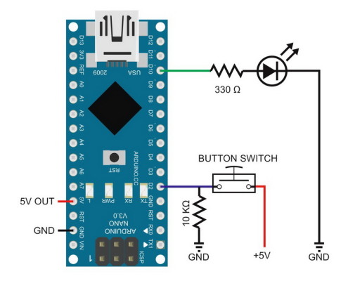 To make it easy for beginners, this tutorial uses the simplest method: initializes the Arduino pin as an internal pull-up input without using the external resistor. Tell me in the comment. Put the three zeros after the first two digits and we get 10,000 or 10k. Afterwards, push the button to verify that the pins are now electrically joined. The button is also called pushbutton, tactile button or momentary switch. As can be seen in the image, opposite pins are electrically connected and essentially one piece of metal. Very interesting & neat project. To check the status of any pin whether it is HIGH or LOW we use the function digitalRead().
  The delay() function is passed a value of 1 to generate a 1ms delay between each pass through the loop. The Momentary switches work only as long as you press on them. The letter k in 10k is short for kilo which means 1000. This tutorial can be a bit longer as I am going to explain the extreme basics. The on-board LED switches on when the push button switch is closed, and switches off when the push button switch is released, or opened. The same connections will also work with the Mega. As you can see currently inside this loop we have only two IF conditions. The DigitalReadSerial example sketch sends the state of the switch out of the Arduino USB port. This is done using the = assignment operator. Please make a donation to help cover our hosting and other costs. Open the serial monitor window from the Arduino IDE to see the state of the switch that is sent from the Arduino. On the other hand, when the switch is closed, it sends a 1 out of the USB port. A Push Button is used to complete an electric circuit when you press on it. Each button needs its own Digital Pin; we picked 2, 3, 4, and 5 for the four buttons that we are using, but any of the Digital Pins will work. This is all we need in our void setup() function. When the button is pushed, the metal strips electrically join together. The following image is a circuit diagram of the previous two breadboard circuits. As soon as the button is release the sflag status is changed from 1 to zero. Test the functionality of the switch with the multimeter afterwards. Constant buttonPin is assigned a value of 2 and ledPin is assigned a value of 13. See the article on basic continuity testing with a multimeter. I have been doing Job in UAE as a site engineer in an Electrical Construction Company. This can be a great way to expand your coding knowledge. (adsbygoogle = window.adsbygoogle || []).push({}); Please Note: these are affiliate links. 5V from the top right of the board is first connected to the positive horizontal rail of the breadboard. // initialize serial communication at 9600 bits per second: // initialize the pushbutton pin as an pull-up input. You can easily expand on what you have made with additional components, giving you the chance to explore a wealth of exciting ideas and create things that make you feel proud. kw8 }~WM8xJNI:HHbBmfv* $(Q~t{'[&A< Push buttons are most commonly used in Calculators, cell phones, TV remote controllers, kitchen appliances, industrial machines, keypads etc. A push button switch called a momentary push button switch is used in this tutorial. Serial.println() is a function that sends a value out of the serial/USB port. Basic Push Button program to control an LED. In this tutorial, a pull-down resistor is used in conjunction with the push button switch.
 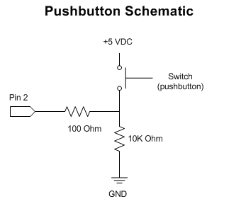 Code from the Button sketch is listed below for reference. Secondly, plug the 10k resistor into the breadboard as shown in the image. This causes the code between the braces that follow the else keyword to run instead. Pull-down describes the function of the resistor in the circuit, it is not a special type of resistor. * Watching Movies
As you can see I have added a 10k resistor, which is also known as the Pulldown resistor. In fact a 10k resistor is used in the circuit. When the switch is closed, 5V is attached to pin 2 of the Arduino. Refer back to Arduino Serial Monitor for Beginners, which is part 4 of this tutorial for an explanation of how to use the serial monitor. This is the basic and simplest connection diagram that I can start with. Both constant values are integers, which means that they have to be assigned values that are whole numbers and not fractions. In the above code, the keyword const means constant, and int means integer. Inside a Push Button there is a small spring which makes contact with two wires, allowing electricity to flow when you press it. @^(^.l}mNzU%T=|OCNx(f=~*HGz=jCVjljwTGql\V,u4w Km}!5qcjz.7+pAiOQ;U>KX@^ X7},}wa-:d rQO7o?__.]%Yn9|rp,vg/K3m,b37i$bVh^w-6$<5Xm|(}
]L!qZs 0de2Y26OOi'f8fN, As the Push Button is an input device or component, thats why it is set to input. Any electronic component or device that you want to use with the Arduino Uno or Mega or any other controller board, you will need to define a pin for that component or device. This means that the resistor value starts with 10. You know, Push Button is also a sensor. Example sketch code reads the switch or button state to determine whether the switch is open or closed. Most impressed with the My name is Shahzada Fahad and I am an Electrical Engineer. To make it much easier for beginners, especially when using multiple buttons, we created a library, called ezButton. The first time it is called, it sets up the on-board LED pin as an output pin. The void setup function is executed only one time when the Arduino or Mega board is first turned ON. Put your multimeter onto the continuity setting. Push Button connection with Arduino Uno or Mega. Again, this is by convention and any color wire can be used instead if a red wire is not available. These are the push-button switch and the on-board LED. Most electronic products have a reset button. An article on the basics of switches for beginners shows different symbols used for switches in circuit diagrams. The difference is that the integer variable buttonState is defined in the loop() function and assigned the return value of digitalRead() in the same line. There are two ways to use a button with Arduino: If we do NOT use neither pull-down nor pull-up resistor, the state of the input pin is floating when the button is NOT pressed.
Code from the Button sketch is listed below for reference. Secondly, plug the 10k resistor into the breadboard as shown in the image. This causes the code between the braces that follow the else keyword to run instead. Pull-down describes the function of the resistor in the circuit, it is not a special type of resistor. * Watching Movies
As you can see I have added a 10k resistor, which is also known as the Pulldown resistor. In fact a 10k resistor is used in the circuit. When the switch is closed, 5V is attached to pin 2 of the Arduino. Refer back to Arduino Serial Monitor for Beginners, which is part 4 of this tutorial for an explanation of how to use the serial monitor. This is the basic and simplest connection diagram that I can start with. Both constant values are integers, which means that they have to be assigned values that are whole numbers and not fractions. In the above code, the keyword const means constant, and int means integer. Inside a Push Button there is a small spring which makes contact with two wires, allowing electricity to flow when you press it. @^(^.l}mNzU%T=|OCNx(f=~*HGz=jCVjljwTGql\V,u4w Km}!5qcjz.7+pAiOQ;U>KX@^ X7},}wa-:d rQO7o?__.]%Yn9|rp,vg/K3m,b37i$bVh^w-6$<5Xm|(}
]L!qZs 0de2Y26OOi'f8fN, As the Push Button is an input device or component, thats why it is set to input. Any electronic component or device that you want to use with the Arduino Uno or Mega or any other controller board, you will need to define a pin for that component or device. This means that the resistor value starts with 10. You know, Push Button is also a sensor. Example sketch code reads the switch or button state to determine whether the switch is open or closed. Most impressed with the My name is Shahzada Fahad and I am an Electrical Engineer. To make it much easier for beginners, especially when using multiple buttons, we created a library, called ezButton. The first time it is called, it sets up the on-board LED pin as an output pin. The void setup function is executed only one time when the Arduino or Mega board is first turned ON. Put your multimeter onto the continuity setting. Push Button connection with Arduino Uno or Mega. Again, this is by convention and any color wire can be used instead if a red wire is not available. These are the push-button switch and the on-board LED. Most electronic products have a reset button. An article on the basics of switches for beginners shows different symbols used for switches in circuit diagrams. The difference is that the integer variable buttonState is defined in the loop() function and assigned the return value of digitalRead() in the same line. There are two ways to use a button with Arduino: If we do NOT use neither pull-down nor pull-up resistor, the state of the input pin is floating when the button is NOT pressed.  Having started businesses in the fields of web development and 3D printing, along with working as a writer for many years, Samuel offers a unique insight into the world of technology. Now lets start with the very basic connection diagram and Arduino program. Button usually have four pins.if(typeof ez_ad_units != 'undefined'){ez_ad_units.push([[728,90],'arduinogetstarted_com-medrectangle-4','ezslot_8',116,'0','0'])};if(typeof __ez_fad_position != 'undefined'){__ez_fad_position('div-gpt-ad-arduinogetstarted_com-medrectangle-4-0')}; However, these pins are internally connected in pairs.
  The beginners do NOT need to care about how to wire the pull-up/pull-down resistor. The beginners just need to use the Arduino code.if(typeof ez_ad_units != 'undefined'){ez_ad_units.push([[300,250],'arduinogetstarted_com-leader-3','ezslot_9',120,'0','0'])};if(typeof __ez_fad_position != 'undefined'){__ez_fad_position('div-gpt-ad-arduinogetstarted_com-leader-3-0')}; Image is developed using Fritzing. As you can see for now I am not using any Pull Up resistor with the Push Button. During the testing you will come to know, while using the Push Button, you do not get a clean closed contact when you press the Push Button Switch, you get a very short transition period where the switch very quickly closes, opens, closes, opens and closes before settling down and becoming fully closed. A Push Button is made up of hard material usually plastic or metal. In this case, the Arduino sees 5V on pin 2. One more thing that I would like to talk about, I am sure you might be thinking about, why I have connected ground with the Push Button switch? The above line of code defines an integer variable called buttonState and assigns it an initial value of 0. In other words, whether the buttonState variable contains a value of HIGH or LOW. Now lets write a very basic Arduino program which turns on the LED when we press the push button switch and turns OFF the LED as we release the pressure applied on the Push Button. Share with your friends to help us spread the tutorial! We just need four lines of code: one for each of the buttons that we have attached to our Arduino. Instead of using the PULLUP resistor externally, we can also use the Arduinos internal pull up resistor. We took a lot of time and effort to create the content of this tutorial, please respect our work! (buttonState == HIGH) means: Does the variable buttonState contain the value HIGH? * Travelling
Starting Electronics needs your help! There are many solutions both on the hardware side and on the software side, called debouncing. The following image shows how to connect a push button switch to an Arduino Uno using a pull-down resistor.
The beginners do NOT need to care about how to wire the pull-up/pull-down resistor. The beginners just need to use the Arduino code.if(typeof ez_ad_units != 'undefined'){ez_ad_units.push([[300,250],'arduinogetstarted_com-leader-3','ezslot_9',120,'0','0'])};if(typeof __ez_fad_position != 'undefined'){__ez_fad_position('div-gpt-ad-arduinogetstarted_com-leader-3-0')}; Image is developed using Fritzing. As you can see for now I am not using any Pull Up resistor with the Push Button. During the testing you will come to know, while using the Push Button, you do not get a clean closed contact when you press the Push Button Switch, you get a very short transition period where the switch very quickly closes, opens, closes, opens and closes before settling down and becoming fully closed. A Push Button is made up of hard material usually plastic or metal. In this case, the Arduino sees 5V on pin 2. One more thing that I would like to talk about, I am sure you might be thinking about, why I have connected ground with the Push Button switch? The above line of code defines an integer variable called buttonState and assigns it an initial value of 0. In other words, whether the buttonState variable contains a value of HIGH or LOW. Now lets write a very basic Arduino program which turns on the LED when we press the push button switch and turns OFF the LED as we release the pressure applied on the Push Button. Share with your friends to help us spread the tutorial! We just need four lines of code: one for each of the buttons that we have attached to our Arduino. Instead of using the PULLUP resistor externally, we can also use the Arduinos internal pull up resistor. We took a lot of time and effort to create the content of this tutorial, please respect our work! (buttonState == HIGH) means: Does the variable buttonState contain the value HIGH? * Travelling
Starting Electronics needs your help! There are many solutions both on the hardware side and on the software side, called debouncing. The following image shows how to connect a push button switch to an Arduino Uno using a pull-down resistor. 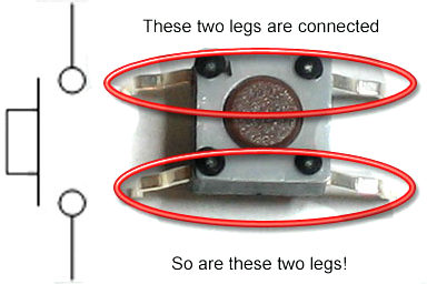 ArduinoGetStarted.com is a participant in the Amazon Services LLC Associates Program, an affiliate advertising program designed to provide a means for sites to earn advertising fees by advertising and linking to Amazon.com, Amazon.it, Amazon.fr, Amazon.co.uk, Amazon.ca, Amazon.de, Amazon.es and Amazon.co.jp. If buttonState does contain HIGH, the expression (buttonState == HIGH) is said to have evaluated to true. In the setup() part of the sketch, pinMode() is used to set pin 2 up as an input again, as was done in the Button sketch. One button's pin is connected to VCC or GND. It is a basic component and widely used in many Arduino projects. The working principle of all the Push buttons is exactly the same. As you can see in the circuit diagram above the Push Button Switch is connected with the ground. You can turn ON and turn OFF the LED without any false switching. You can share the link of this tutorial anywhere. A logic high state is referred to as HIGH or 1 in an Arduino sketch. It means the state can be HIGH or LOW (unstable, unfixed), resulting in the wrong detection. Depending on the application, we choose one of them.
 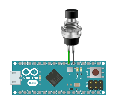 Why we use a resistor with the Push Button? When you press the button it gives 5 volts to the Arduino pin and when you release the button it gives ground to the Arduinos pin. Some Push Buttons have 2 legs, some have 3 legs, and some have 4 legs or even more. To avoid using a long wire from the 5V pin at the bottom left of the board, 5V is taken from the top right of the board instead. In addition to this, the second value passed to pinMode() is INPUT. These IF conditions are used to check if the button is pressed or not. After uploading the sketch to the Arduino board, the TX LED appears to be on. Lastly, connect the 5V Arduino pin to a push button pin as the red wire shows in the image. Each part of the sketch is explained under the sub-headings. This is a current limiting resistor. The reason for this is that the TX or transmit LED indicates that the Arduino is transmitting on the USB port. Open the Arduino IDE and select File Examples 02.Digital Button from the top menu bar. The following checks if the button is released.
  How to use the Arduinos Internal Pull Up resistor. The code between the braces switches the on-board LED off. Outside of work, Samuel can usually be found cycling, playing PC video games, or desperately attempting to communicate with his pet crab. Because the state of the push button (open or closed) changes while the sketch is running, its state is saved to the buttonState integer variable. Wherever ledPin is used, 13 is placed. A logic low state is referred to as LOW or 0. Release the switch, and the value in the serial monitor window changes back to 0. What the above two lines of code do is define two constant values called buttonPin and ledPin. In the loop() function of the sketch, the state of the button is read again, as before. The data that is transmitted is the state of the switch.
  The value returned is assigned to the buttonState variable. You only need a handful of parts to complete this project, many of which you will already have in your DIY parts collection. For example, in case of using a button to control an LED: 1 is HIGH, 0 is LOW.if(typeof ez_ad_units != 'undefined'){ez_ad_units.push([[728,90],'arduinogetstarted_com-mobile-leaderboard-1','ezslot_11',106,'0','0'])};if(typeof __ez_fad_position != 'undefined'){__ez_fad_position('div-gpt-ad-arduinogetstarted_com-mobile-leaderboard-1-0')}; Read the line-by-line explanation in comment lines of code! So it means in this example we are giving ground as the signal to the Arduino pin. Integer variables are used in a sketch to hold a value that can change while the sketch is running. In other words, test between pins on the same side of the switch to verify that they are open circuit. Push Button is connected with the Arduinos pin number 2.
  This time the circuit will be a little bit modified. Both sketches in this part of the tutorial determine if a switch is open or closed by reading the logic state applied to a digital input pin. Why I have not connected 5 volts with the Push Button? This example without the button debouncing will not be accurate, so, I am going to use the button debouncing as well to get 100% accurate result. But how exactly can you wire and program more than one push-button to work with your Arduino? Our if statement checks the state of the button using the built-in digitalRead function. This is the normal behavior of the button. Dubai Virtual Asset License: Why OKX May Be the Next Big Exchange, Is It Worth Buying a Fitness Tracker? Howerver, please do not copy the content to share on other websites. If you think the video tutorials are essential, please subscribe to our YouTube channel to give us motivation for making the videos. An LED is connected with pin number 13 of the Arduino through a 330 ohm resistor. This just gives the push button switch on pin 2 and the built-in LED on pin 13 meaningful names.
  The purpose of this construct is to determine whether the switch is open or closed. As can be seen in the following image, pins opposite each other on a push button switch are connected. This is a simple project that is designed to get you started with more complex Arduino builds in the future. Release the button and the connection is broken again. Open the serial monitor window, and the value sent is displayed. Arduino Push Button Switch wiring and code this is a very detailed getting started tutorial on How to use a Push Button Switch with Arduino Uno. Sometimes when you press the Push Button instead of turning OFF the LED it will turn ON the LED and this is just because of the switch bounce phenomena. For the best explanation I am going to use the Proteus simulation software. The button is released.
  // constants won't change. As was already mentioned in a previous part of this tutorial on how to build a breadboard circuit for beginners, there are many ways to build the same circuit on a breadboard. You can learn about ezButton library here. I will explain both the types. This is called the switch bounce. * Martial Arts
// the pull-up input pin will be HIGH when the switch is open and LOW when the switch is closed. Samuel is a UK-based technology writer with a passion for all things DIY. Click the donate button to send a donation of any amount. Later in the sketch, when the state of the switch on pin 2 is read, it will have a value of 0 if open, and 1 if closed. Finally, Serial.println() is called, followed by the delay() function.
// constants won't change. As was already mentioned in a previous part of this tutorial on how to build a breadboard circuit for beginners, there are many ways to build the same circuit on a breadboard. You can learn about ezButton library here. I will explain both the types. This is called the switch bounce. * Martial Arts
// the pull-up input pin will be HIGH when the switch is open and LOW when the switch is closed. Samuel is a UK-based technology writer with a passion for all things DIY. Click the donate button to send a donation of any amount. Later in the sketch, when the state of the switch on pin 2 is read, it will have a value of 0 if open, and 1 if closed. Finally, Serial.println() is called, followed by the delay() function.  As you can see in the circuit diagram above, this time I am using 5 volts as the signal to the Arduino. If the sensor has either closed (connected to, If the sensor has two defined voltage levels (. The second call to pinMode() is passed the constant integer buttonPin, which resolves to 2. Even you pressed and released the button only once, the output in Serial Monitor may show several pressed and release events. This opens the Arduino Button sketch from the built in examples. There are four ways (actually two ways because of symmetry) to connect to button (see image). A 5% tolerance 10k resistor has the colors brown, black and orange, as shown in the image below. This opens the DigitalReadSerial example sketch. As you can see one side of the Push Button is connected with the ground while the other side of the Push Button Switch is connected with the Arduinos pin number 2. Press the push button that is attached to pin 2 of the Arduino. Arduino Push Button Tutorial Description: PULLDOWN & PULLUP resistors with the Push Button: PULLDOWN Resistor with Push Button Video: PULLUP Resistor with Push Button Arduino Programming: Arduino internal PULLUP resistor programming: Arduino Push Button Toggle Switch programming: how a 10k resistor is used with the push button, how to connect a push button with arduino, how to control a an led using push button, how to use a resistor with the push button, AMD Ryzen 7 Pro 6850U Complete review with benchmarks, Arduino Fingerprint Door Lock, Android biometric, Fingerprint app lock, Introduction to Casing Capping Wiring System, Android app development to control Arduino over Bluetooth using Android Studio, Soil NPK Sensor with Arduino and Android Cell Phone Application for monitoring Soil Nutrient, Arduino esp8266 wifi Home/Office Automation System, IOT based Car Parking System using Arduino and Nodemcu esp8266, How to Create Android App for Arduino Sensor Monitoring over Bluetooth, Qualcomm Snapdragon 680 Complete review with benchmarks, Arduino Libraries Download and Projects they are used in Project codes, Electric Motor Tripping Reasons and How to fix them, Star Delta Motors, LM358 IC Pin Configuration, Working, LM358 Circuit Examples, pH meter Arduino, pH Meter Calibration, DIYMORE pH Sensor Arduino Code, Arduino DC Motor Speed Control with Encoder, Arduino DC Motor Encoder, SOP and POS Digital Logic Designing with solved examples, 500W Ebike Brushless Motor Controller wiring explanation, Hoverboard Test, Google Spreadsheet or Google Sheets with ESP8266 Nodemcu for Data Logging, Decoder, 3 to 8 Decoder Block Diagram, Truth Table, and Logic Diagram, Max30100 pulse Oximeter Arduino Code, circuit, and Programming, Arduino CNC Shield V3.0 and A4988 Hybrid Stepper Motor Driver + Joystick, Control Position and Speed of Stepper Motor using Android Bluetooth App, A4988 Driver, & Arduino, MIT APP inventor Arduino Bluetooth Application Making Explained, Android Activity: Basic usage of Android activities, Toast Message & Menu, Android Intent: Explicit Intent and Implicit Intent, Android Listview: Custom ListView and onClick Event on ListView. this time I defined the following two variables flag and sflag. After uploading the sketch, press the push button switch on the breadboard to close the switch. As you know LED is an output device so, thats why the LED is set to output using the pinMode function. Part 8 of the Arduino Tutorial for Beginners. The image below shows examples of this type of switch. 0z;6)BS-Oe For example, the same circuits above are built differently in the Button example from Arduino.
 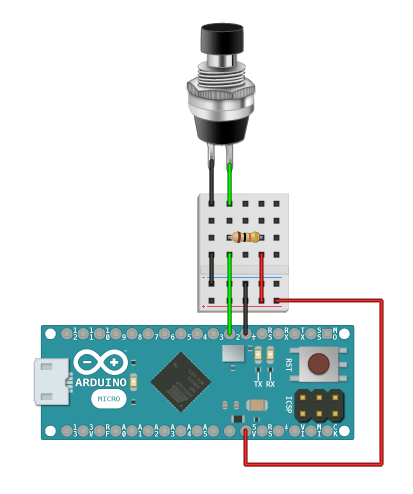 There is more than one way to connect a push button switch to an Arduino. So how this works?
 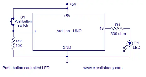 It is passed the constant integer buttonPin, which resolves to 2. Copyright 2021 ArduinoGetStarted.com. Additionally, the button also keeps other functionalities in many products. As you can see this program is exactly the same as the previous one, but with only two modifications which you can find in the programming. Afterwards, load a sketch that reads the state of the switch. What Is a Transistor and What Is It Used For? Momentary means that the switch stays closed only while pushed.
  As with the previous Button sketch, pin 2 is given a name. We place our main code inside this loop.
  The following condition is used to check if the Push Button is pressed and the flag is zero and the sflag is also zero, which means that the button is pressed. In addition to setting up the pin, the serial port is set up by calling the Serial.begin() function or method. if( (digitalRead(PUSH_BUTTON) == HIGH)) // if the button is not pressed.
  The flag status is changed from 0 to 1, the LED is turned on and the sflag status is also changed from 0 to 1. if( (digitalRead(PUSH_BUTTON) == LOW) && (flag == 0) && (sflag == 0) ). At the start of the loop() function, a function called digitalRead() is called. It is passed the constant integer ledPin which resolves to 13. [ C54(uzQleXXOqfnOnN3DTdN`vw26N
1xjVZ|;`(vgnNf-, kd0*#^h Connect Arduino digital pin 2 to the push button switch as the green wire shows in the image. In the next example I am going to use the Push Button as the Toggle switch. Push Buttons are available in different shapes, sizes, and colors. Use a push button switch with Arduino in this part of the Arduino tutorial for beginners. Learn how to connect multiple push-buttons to an Arduino and check for them being pressed in a program. One time you press the button the LED is turned ON and the second time you press the Push Button the LED is turned OFF. With one button wired up, its time to add the others.
The flag status is changed from 0 to 1, the LED is turned on and the sflag status is also changed from 0 to 1. if( (digitalRead(PUSH_BUTTON) == LOW) && (flag == 0) && (sflag == 0) ). At the start of the loop() function, a function called digitalRead() is called. It is passed the constant integer ledPin which resolves to 13. [ C54(uzQleXXOqfnOnN3DTdN`vw26N
1xjVZ|;`(vgnNf-, kd0*#^h Connect Arduino digital pin 2 to the push button switch as the green wire shows in the image. In the next example I am going to use the Push Button as the Toggle switch. Push Buttons are available in different shapes, sizes, and colors. Use a push button switch with Arduino in this part of the Arduino tutorial for beginners. Learn how to connect multiple push-buttons to an Arduino and check for them being pressed in a program. One time you press the button the LED is turned ON and the second time you press the Push Button the LED is turned OFF. With one button wired up, its time to add the others.
The following image shows an equivalent push button circuit for an Arduino MEGA 2560 board. The push button switch on the left shows the orientation of the push button, which is the orientation of both push buttons in the image. Now that your Arduino is all wired up, it is time to start working on the code. The Button sketch is broken up into parts and placed under various sub-headings that follow. In other words, digitalRead() reads the current state of the switch attached to digital pin 2. Get a momentary push button switch ready to plug into the breadboard circuit. Toggle switches are most commonly used in load automation projects where you need to turn ON and turn OFF a load using only one Push Button. They're used here to set pin numbers: // the current reading from the input pin. After building the circuit shown in the previous section, upload the Button example sketch to the target Arduino board. There is also a DigitalReadSerial Arduino page on the Arduino website. New Book: Explore ATtiny Microcontrollers using C and Assembly Language. The following code contains comments that explain what the code does. In the Arduino IDE, select File Examples 01.Basics DigitalReadSerial from the top menu bar. To make it easy for beginners, this tutorial uses the simplest method: initializes the Arduino pin as an internal pull-up input without using the external resistor. Tell me in the comment. Put the three zeros after the first two digits and we get 10,000 or 10k. Afterwards, push the button to verify that the pins are now electrically joined. The button is also called pushbutton, tactile button or momentary switch. As can be seen in the image, opposite pins are electrically connected and essentially one piece of metal. Very interesting & neat project. To check the status of any pin whether it is HIGH or LOW we use the function digitalRead(). The delay() function is passed a value of 1 to generate a 1ms delay between each pass through the loop. The Momentary switches work only as long as you press on them. The letter k in 10k is short for kilo which means 1000. This tutorial can be a bit longer as I am going to explain the extreme basics. The on-board LED switches on when the push button switch is closed, and switches off when the push button switch is released, or opened. The same connections will also work with the Mega. As you can see currently inside this loop we have only two IF conditions. The DigitalReadSerial example sketch sends the state of the switch out of the Arduino USB port. This is done using the = assignment operator. Please make a donation to help cover our hosting and other costs. Open the serial monitor window from the Arduino IDE to see the state of the switch that is sent from the Arduino. On the other hand, when the switch is closed, it sends a 1 out of the USB port. A Push Button is used to complete an electric circuit when you press on it. Each button needs its own Digital Pin; we picked 2, 3, 4, and 5 for the four buttons that we are using, but any of the Digital Pins will work. This is all we need in our void setup() function. When the button is pushed, the metal strips electrically join together. The following image is a circuit diagram of the previous two breadboard circuits. As soon as the button is release the sflag status is changed from 1 to zero. Test the functionality of the switch with the multimeter afterwards. Constant buttonPin is assigned a value of 2 and ledPin is assigned a value of 13. See the article on basic continuity testing with a multimeter. I have been doing Job in UAE as a site engineer in an Electrical Construction Company. This can be a great way to expand your coding knowledge. (adsbygoogle = window.adsbygoogle || []).push({}); Please Note: these are affiliate links. 5V from the top right of the board is first connected to the positive horizontal rail of the breadboard. // initialize serial communication at 9600 bits per second: // initialize the pushbutton pin as an pull-up input. You can easily expand on what you have made with additional components, giving you the chance to explore a wealth of exciting ideas and create things that make you feel proud. kw8 }~WM8xJNI:HHbBmfv* $(Q~t{'[&A< Push buttons are most commonly used in Calculators, cell phones, TV remote controllers, kitchen appliances, industrial machines, keypads etc. A push button switch called a momentary push button switch is used in this tutorial. Serial.println() is a function that sends a value out of the serial/USB port. Basic Push Button program to control an LED. In this tutorial, a pull-down resistor is used in conjunction with the push button switch. Code from the Button sketch is listed below for reference. Secondly, plug the 10k resistor into the breadboard as shown in the image. This causes the code between the braces that follow the else keyword to run instead. Pull-down describes the function of the resistor in the circuit, it is not a special type of resistor. * Watching Movies
As you can see I have added a 10k resistor, which is also known as the Pulldown resistor. In fact a 10k resistor is used in the circuit. When the switch is closed, 5V is attached to pin 2 of the Arduino. Refer back to Arduino Serial Monitor for Beginners, which is part 4 of this tutorial for an explanation of how to use the serial monitor. This is the basic and simplest connection diagram that I can start with. Both constant values are integers, which means that they have to be assigned values that are whole numbers and not fractions. In the above code, the keyword const means constant, and int means integer. Inside a Push Button there is a small spring which makes contact with two wires, allowing electricity to flow when you press it. @^(^.l}mNzU%T=|OCNx(f=~*HGz=jCVjljwTGql\V,u4w Km}!5qcjz.7+pAiOQ;U>KX@^ X7},}wa-:d rQO7o?__.]%Yn9|rp,vg/K3m,b37i$bVh^w-6$<5Xm|(}
]L!qZs 0de2Y26OOi'f8fN, As the Push Button is an input device or component, thats why it is set to input. Any electronic component or device that you want to use with the Arduino Uno or Mega or any other controller board, you will need to define a pin for that component or device. This means that the resistor value starts with 10. You know, Push Button is also a sensor. Example sketch code reads the switch or button state to determine whether the switch is open or closed. Most impressed with the My name is Shahzada Fahad and I am an Electrical Engineer. To make it much easier for beginners, especially when using multiple buttons, we created a library, called ezButton. The first time it is called, it sets up the on-board LED pin as an output pin. The void setup function is executed only one time when the Arduino or Mega board is first turned ON. Put your multimeter onto the continuity setting. Push Button connection with Arduino Uno or Mega. Again, this is by convention and any color wire can be used instead if a red wire is not available. These are the push-button switch and the on-board LED. Most electronic products have a reset button. An article on the basics of switches for beginners shows different symbols used for switches in circuit diagrams. The difference is that the integer variable buttonState is defined in the loop() function and assigned the return value of digitalRead() in the same line. There are two ways to use a button with Arduino: If we do NOT use neither pull-down nor pull-up resistor, the state of the input pin is floating when the button is NOT pressed. Having started businesses in the fields of web development and 3D printing, along with working as a writer for many years, Samuel offers a unique insight into the world of technology. Now lets start with the very basic connection diagram and Arduino program. Button usually have four pins.if(typeof ez_ad_units != 'undefined'){ez_ad_units.push([[728,90],'arduinogetstarted_com-medrectangle-4','ezslot_8',116,'0','0'])};if(typeof __ez_fad_position != 'undefined'){__ez_fad_position('div-gpt-ad-arduinogetstarted_com-medrectangle-4-0')}; However, these pins are internally connected in pairs. The beginners do NOT need to care about how to wire the pull-up/pull-down resistor. The beginners just need to use the Arduino code.if(typeof ez_ad_units != 'undefined'){ez_ad_units.push([[300,250],'arduinogetstarted_com-leader-3','ezslot_9',120,'0','0'])};if(typeof __ez_fad_position != 'undefined'){__ez_fad_position('div-gpt-ad-arduinogetstarted_com-leader-3-0')}; Image is developed using Fritzing. As you can see for now I am not using any Pull Up resistor with the Push Button. During the testing you will come to know, while using the Push Button, you do not get a clean closed contact when you press the Push Button Switch, you get a very short transition period where the switch very quickly closes, opens, closes, opens and closes before settling down and becoming fully closed. A Push Button is made up of hard material usually plastic or metal. In this case, the Arduino sees 5V on pin 2. One more thing that I would like to talk about, I am sure you might be thinking about, why I have connected ground with the Push Button switch? The above line of code defines an integer variable called buttonState and assigns it an initial value of 0. In other words, whether the buttonState variable contains a value of HIGH or LOW. Now lets write a very basic Arduino program which turns on the LED when we press the push button switch and turns OFF the LED as we release the pressure applied on the Push Button. Share with your friends to help us spread the tutorial! We just need four lines of code: one for each of the buttons that we have attached to our Arduino. Instead of using the PULLUP resistor externally, we can also use the Arduinos internal pull up resistor. We took a lot of time and effort to create the content of this tutorial, please respect our work! (buttonState == HIGH) means: Does the variable buttonState contain the value HIGH? * Travelling
Starting Electronics needs your help! There are many solutions both on the hardware side and on the software side, called debouncing. The following image shows how to connect a push button switch to an Arduino Uno using a pull-down resistor. ArduinoGetStarted.com is a participant in the Amazon Services LLC Associates Program, an affiliate advertising program designed to provide a means for sites to earn advertising fees by advertising and linking to Amazon.com, Amazon.it, Amazon.fr, Amazon.co.uk, Amazon.ca, Amazon.de, Amazon.es and Amazon.co.jp. If buttonState does contain HIGH, the expression (buttonState == HIGH) is said to have evaluated to true. In the setup() part of the sketch, pinMode() is used to set pin 2 up as an input again, as was done in the Button sketch. One button's pin is connected to VCC or GND. It is a basic component and widely used in many Arduino projects. The working principle of all the Push buttons is exactly the same. As you can see in the circuit diagram above the Push Button Switch is connected with the ground. You can turn ON and turn OFF the LED without any false switching. You can share the link of this tutorial anywhere. A logic high state is referred to as HIGH or 1 in an Arduino sketch. It means the state can be HIGH or LOW (unstable, unfixed), resulting in the wrong detection. Depending on the application, we choose one of them. Why we use a resistor with the Push Button? When you press the button it gives 5 volts to the Arduino pin and when you release the button it gives ground to the Arduinos pin. Some Push Buttons have 2 legs, some have 3 legs, and some have 4 legs or even more. To avoid using a long wire from the 5V pin at the bottom left of the board, 5V is taken from the top right of the board instead. In addition to this, the second value passed to pinMode() is INPUT. These IF conditions are used to check if the button is pressed or not. After uploading the sketch to the Arduino board, the TX LED appears to be on. Lastly, connect the 5V Arduino pin to a push button pin as the red wire shows in the image. Each part of the sketch is explained under the sub-headings. This is a current limiting resistor. The reason for this is that the TX or transmit LED indicates that the Arduino is transmitting on the USB port. Open the Arduino IDE and select File Examples 02.Digital Button from the top menu bar. The following checks if the button is released. How to use the Arduinos Internal Pull Up resistor. The code between the braces switches the on-board LED off. Outside of work, Samuel can usually be found cycling, playing PC video games, or desperately attempting to communicate with his pet crab. Because the state of the push button (open or closed) changes while the sketch is running, its state is saved to the buttonState integer variable. Wherever ledPin is used, 13 is placed. A logic low state is referred to as LOW or 0. Release the switch, and the value in the serial monitor window changes back to 0. What the above two lines of code do is define two constant values called buttonPin and ledPin. In the loop() function of the sketch, the state of the button is read again, as before. The data that is transmitted is the state of the switch. The value returned is assigned to the buttonState variable. You only need a handful of parts to complete this project, many of which you will already have in your DIY parts collection. For example, in case of using a button to control an LED: 1 is HIGH, 0 is LOW.if(typeof ez_ad_units != 'undefined'){ez_ad_units.push([[728,90],'arduinogetstarted_com-mobile-leaderboard-1','ezslot_11',106,'0','0'])};if(typeof __ez_fad_position != 'undefined'){__ez_fad_position('div-gpt-ad-arduinogetstarted_com-mobile-leaderboard-1-0')}; Read the line-by-line explanation in comment lines of code! So it means in this example we are giving ground as the signal to the Arduino pin. Integer variables are used in a sketch to hold a value that can change while the sketch is running. In other words, test between pins on the same side of the switch to verify that they are open circuit. Push Button is connected with the Arduinos pin number 2. This time the circuit will be a little bit modified. Both sketches in this part of the tutorial determine if a switch is open or closed by reading the logic state applied to a digital input pin. Why I have not connected 5 volts with the Push Button? This example without the button debouncing will not be accurate, so, I am going to use the button debouncing as well to get 100% accurate result. But how exactly can you wire and program more than one push-button to work with your Arduino? Our if statement checks the state of the button using the built-in digitalRead function. This is the normal behavior of the button. Dubai Virtual Asset License: Why OKX May Be the Next Big Exchange, Is It Worth Buying a Fitness Tracker? Howerver, please do not copy the content to share on other websites. If you think the video tutorials are essential, please subscribe to our YouTube channel to give us motivation for making the videos. An LED is connected with pin number 13 of the Arduino through a 330 ohm resistor. This just gives the push button switch on pin 2 and the built-in LED on pin 13 meaningful names. The purpose of this construct is to determine whether the switch is open or closed. As can be seen in the following image, pins opposite each other on a push button switch are connected. This is a simple project that is designed to get you started with more complex Arduino builds in the future. Release the button and the connection is broken again. Open the serial monitor window, and the value sent is displayed. Arduino Push Button Switch wiring and code this is a very detailed getting started tutorial on How to use a Push Button Switch with Arduino Uno. Sometimes when you press the Push Button instead of turning OFF the LED it will turn ON the LED and this is just because of the switch bounce phenomena. For the best explanation I am going to use the Proteus simulation software. The button is released. // constants won't change. As was already mentioned in a previous part of this tutorial on how to build a breadboard circuit for beginners, there are many ways to build the same circuit on a breadboard. You can learn about ezButton library here. I will explain both the types. This is called the switch bounce. * Martial Arts
// the pull-up input pin will be HIGH when the switch is open and LOW when the switch is closed. Samuel is a UK-based technology writer with a passion for all things DIY. Click the donate button to send a donation of any amount. Later in the sketch, when the state of the switch on pin 2 is read, it will have a value of 0 if open, and 1 if closed. Finally, Serial.println() is called, followed by the delay() function. As you can see in the circuit diagram above, this time I am using 5 volts as the signal to the Arduino. If the sensor has either closed (connected to, If the sensor has two defined voltage levels (. The second call to pinMode() is passed the constant integer buttonPin, which resolves to 2. Even you pressed and released the button only once, the output in Serial Monitor may show several pressed and release events. This opens the Arduino Button sketch from the built in examples. There are four ways (actually two ways because of symmetry) to connect to button (see image). A 5% tolerance 10k resistor has the colors brown, black and orange, as shown in the image below. This opens the DigitalReadSerial example sketch. As you can see one side of the Push Button is connected with the ground while the other side of the Push Button Switch is connected with the Arduinos pin number 2. Press the push button that is attached to pin 2 of the Arduino. Arduino Push Button Tutorial Description: PULLDOWN & PULLUP resistors with the Push Button: PULLDOWN Resistor with Push Button Video: PULLUP Resistor with Push Button Arduino Programming: Arduino internal PULLUP resistor programming: Arduino Push Button Toggle Switch programming: how a 10k resistor is used with the push button, how to connect a push button with arduino, how to control a an led using push button, how to use a resistor with the push button, AMD Ryzen 7 Pro 6850U Complete review with benchmarks, Arduino Fingerprint Door Lock, Android biometric, Fingerprint app lock, Introduction to Casing Capping Wiring System, Android app development to control Arduino over Bluetooth using Android Studio, Soil NPK Sensor with Arduino and Android Cell Phone Application for monitoring Soil Nutrient, Arduino esp8266 wifi Home/Office Automation System, IOT based Car Parking System using Arduino and Nodemcu esp8266, How to Create Android App for Arduino Sensor Monitoring over Bluetooth, Qualcomm Snapdragon 680 Complete review with benchmarks, Arduino Libraries Download and Projects they are used in Project codes, Electric Motor Tripping Reasons and How to fix them, Star Delta Motors, LM358 IC Pin Configuration, Working, LM358 Circuit Examples, pH meter Arduino, pH Meter Calibration, DIYMORE pH Sensor Arduino Code, Arduino DC Motor Speed Control with Encoder, Arduino DC Motor Encoder, SOP and POS Digital Logic Designing with solved examples, 500W Ebike Brushless Motor Controller wiring explanation, Hoverboard Test, Google Spreadsheet or Google Sheets with ESP8266 Nodemcu for Data Logging, Decoder, 3 to 8 Decoder Block Diagram, Truth Table, and Logic Diagram, Max30100 pulse Oximeter Arduino Code, circuit, and Programming, Arduino CNC Shield V3.0 and A4988 Hybrid Stepper Motor Driver + Joystick, Control Position and Speed of Stepper Motor using Android Bluetooth App, A4988 Driver, & Arduino, MIT APP inventor Arduino Bluetooth Application Making Explained, Android Activity: Basic usage of Android activities, Toast Message & Menu, Android Intent: Explicit Intent and Implicit Intent, Android Listview: Custom ListView and onClick Event on ListView. this time I defined the following two variables flag and sflag. After uploading the sketch, press the push button switch on the breadboard to close the switch. As you know LED is an output device so, thats why the LED is set to output using the pinMode function. Part 8 of the Arduino Tutorial for Beginners. The image below shows examples of this type of switch. 0z;6)BS-Oe For example, the same circuits above are built differently in the Button example from Arduino. There is more than one way to connect a push button switch to an Arduino. So how this works? It is passed the constant integer buttonPin, which resolves to 2. Copyright 2021 ArduinoGetStarted.com. Additionally, the button also keeps other functionalities in many products. As you can see this program is exactly the same as the previous one, but with only two modifications which you can find in the programming. Afterwards, load a sketch that reads the state of the switch. What Is a Transistor and What Is It Used For? Momentary means that the switch stays closed only while pushed. As with the previous Button sketch, pin 2 is given a name. We place our main code inside this loop. The following condition is used to check if the Push Button is pressed and the flag is zero and the sflag is also zero, which means that the button is pressed. In addition to setting up the pin, the serial port is set up by calling the Serial.begin() function or method. if( (digitalRead(PUSH_BUTTON) == HIGH)) // if the button is not pressed. The flag status is changed from 0 to 1, the LED is turned on and the sflag status is also changed from 0 to 1. if( (digitalRead(PUSH_BUTTON) == LOW) && (flag == 0) && (sflag == 0) ). At the start of the loop() function, a function called digitalRead() is called. It is passed the constant integer ledPin which resolves to 13. [ C54(uzQleXXOqfnOnN3DTdN`vw26N
1xjVZ|;`(vgnNf-, kd0*#^h Connect Arduino digital pin 2 to the push button switch as the green wire shows in the image. In the next example I am going to use the Push Button as the Toggle switch. Push Buttons are available in different shapes, sizes, and colors. Use a push button switch with Arduino in this part of the Arduino tutorial for beginners. Learn how to connect multiple push-buttons to an Arduino and check for them being pressed in a program. One time you press the button the LED is turned ON and the second time you press the Push Button the LED is turned OFF. With one button wired up, its time to add the others.