This special cable has a 6-pin TC2030-NL Tag-Connector and a 10-pin ribbon connector that mates with the FTSH-105 style micro-headers used for Cortex Debug as found in debuggers such as Keil's ULINK-2. If you want to add a RESET pin, or a logging pin (possibly SWO, but can be custom as well), Conveniently, many of the GDB Server options expose APIs for implementing thread awareness. The 19-Pin Cortex-M Adapter adapts from the 20-pin 0.1'' JTAG connector to a 19-pin 0.05'' Samtec FTSH connector as defined by Arm. The RTOS awareness implementations all wind up looking pretty similar. This solution will help when board space is at a premium and you need a hands free solution for debugging. and then press the connector back in. as power is concerned. Lets trace through a transaction to better understand whats happening end to end. It adapts from the 20-pin 0.1'' JTAG connector to a 19-pin 0.05'' Samtec FTSH connector as defined by Arm. Solutions are also available for either legged or no legs versions of the plug-of-nails target board connectors. Here we propose two simple and cost effective solutions, which do not require soldering, This is quite nice because it means reading state ( memory, registers, etc) over the DAP is pretty much the same operation regardless of the ARM MCU being used. 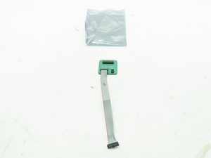 See also the T. The TC2050-IDC-NL-050-ALL programming cable has an 0.050" pitch ribbon connector suitable for programmers and debuggers that use the Samtec FTSH-105-01 style micro-header (10-pins).
 To test it out, start the Saleae trace again and run. Put electrical (insulating) tape around each twisted wire, If the MCU in use has an internal micro flash, many of these probes also come with support for programming that flash so you can easily load new programs on the MCU.
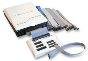
 The "No Legs" versions of our cables are designed to be held in place by hand for a fast programming operation or can be temporarily retained in place for debugging when used with our. The header will bend a little, forcing good electrical connection. The way it works is you provide micro-code that is flashed into RAM to initialize, read, erase, and write to the flash part of interest. Once it has the list, the gdbserver will recover the state of each thread by issuing reads to the memory of the MCU. The only requirements for an AP are that they must: The most common type of Access Port is known as the MEM-AP which exposes an interface to different Memory buses available on a given ARM chip. Then, separate it. however these require a part to be soldered on the board. Sometimes there is a standard 0.05 10 pin ARM debug connector, To make this work, youll need a custom cable. We accept the following cards for on-line payments, no-header-no-brainer-plug-of-nails-footprint-2 - copy. You can test your cable now, before gluing - the header will likely stay in
  In the debuggee VSCode window, load a FW folder/workspace (VSCode remembers the last one) and add the following to debuggee's launch.json. The 19-Pin Cortex-M Adapter allows JTAG, SWD, and SWO connections between J-Link or Flasher and Cortex-M based target hardware systems. So if SWDCLK is running at 500kHz, we want to sample with a rate of at least 2 MegaSamples / second or greater.24 However, the faster we sample, the better our timing resolution will be. There a few common interfaces to the stack: Now that we understand a bit about the software stack in play. By default, pre-releases are disabled. (with the notch facing inside). The idea is to use a standard 2x5 pin 0.05 IDC ARM-Cortex debug connector The TC2050-ARM2010 is a Tag-Connect adapter board allowing our TC2050-IDC cables to be used for ARM JTAG and ARM SWD (Serial Wire Debug) applications. and has zero PCB cost. You will need a 10-pin IDC cable, ARM Cortex-M GDB Debugger support for VSCode, https://github.com/Marus/cortex-debug/wiki/Multi-core-debugging, https://github.com/Marus/cortex-debug/wiki/Disassembly-Debugging, https://developer.arm.com/open-source/gnu-toolchain/gnu-rm/downloads, https://github.com/gnu-mcu-eclipse/openocd/releases, https://github.com/Marus/cortex-debug/wiki, https://github.com/Marus/cortex-debug/blob/master/debug_attributes.md, https://github.com/WebFreak001/code-debug, Support J-Link, OpenOCD GDB Server, pyOCD, Initial support for STMicroelectronic's ST-LINK GDB server (no SWO support yet), Partial support textane/stlink (st-util) GDB Servers (SWO can only be captured via a serial port), Initial support for the Black Magic Probe (This has not been as heavily tested; SWO can only be captured via a serial port), Experimental, coming in V1.2+: Multi-core and multi-session debugging. By default, TRST is not connected, but the Cortex-M adapter comes with a solder bridge (NR1) which allows TRST to be connected to pin 9 of the Cortex-M adapter. Ive run into all of these issues! With either of the cables, you may want to add a momentary switch but they are harder to find).
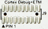


 Then, cut wire number 5, around 10mm from the debugger connector. ARM20 to 6 Pin Plug-of-Nails - With Legs, ARM20 to 10 Pin Plug-of-Nails - With Legs, Cortex 10 Pin to 6 Pin Plug-of-Nails - No Legs, Cortex 10 Pin to 6 Pin Plug-of-Nails - With Legs, Cortex 10 Pin to 10 Pin Plug-of-Nails - No Legs, Cortex 10 Pin to 10 Pin Plug-of-Nails - With Legs, Cortex 10 Pin/SAM LEMTA to 6 Pin Plug-of-Nails - No Legs, Cortex 10 Pin/SAM LEMTA to 6 Pin Plug-of-Nails - With Legs, Cortex 10-pin/SAM LEMTA to 10 Pin Plug-of-Nails - No Legs, Cortex 10-pin/SAM LEMTA to 10 Pin Plug-of-Nails - With Legs, Cortex 20 Pin to 6 Pin Plug-of-Nails - No Legs, Cortex 20 Pin to 6 Pin Plug-of-Nails - With Legs, Cortex 20 Pin to 6 Pin + 10 Pin Plug-of-Nails - With Legs, Cortex 20 Pin to 10 Pin Plug-of-Nail - No Legs, Cortex 20 Pin to 10 Pin Plug-of-Nail - With Legs, PICkit 4 to 6 Pin Plug-of-Nails No Legs (SAM), PICkit 4 to 6 Pin Plug-of-Nails With Legs (SAM), 433 Airport Blvd, Suite 323, Burlingame, CA 94010, USA. Ideal for both debugging and production programming of SAM ARM Cortex MCUs using the Microchip PICkit 4 or SNAP in-circuit debuggers, the 6 pin plug-of-nails cable terminates in a 8 pin 0.1" male SIP strip for connection to the debugger. In this article we will explore the functionality of the DAP. in the GitHub repo. The ones I am aware of and have implemented RTOS plugins with include: A ton of MCUs these days allow one to execute code from external flash parts. Requires only a tiny 0.03" footprint of pads and locating holes in your PCB. It will launch a new window -- the debuggee. Requires only a tiny footprint of pads and locating holes in your PCB. and is usually further reduced by placing the connector in the corner of the board.
  On the nRF52840-DK board I see P18 is labeled as Debug In.
 Lets walk through the transactions that we see. We found Black Magic Probe to work well, and go directly to Target end section. Wrap the whole thing in electrical tape. You usually want to plug it starting from the edge. For a more robust and convenient debugging connection consider using the TC2050 legged cable and footprint. and connect female jumper cables on the long side. Are you confused by all the buzzwords used around embedded debugging (i.e SWD vs JTAG, OpenOCD vs pyOCD vs JLinkGDBServer, CMSIS-DAP vs ST-Link vs J-Link, etc). Ever had issues getting a debugger to flash code? matter if you plug it in from the top or bottom of the board, which is quite Now, insert the header into the connector, aligning the left side with the red wire. 6-Pin "No Legs" TC2030 Plug-of-Nails programming cable for use with ARM Cortex processors. TC2050 10 Pin No legs Plug-of-Nails to 0.050 pitch 10 pin ribbon connector suitable for ULINK2 and similar debuggers that use the Samtec FTSH-105-01 style micro-header. would cause -3V to run through MCU. Subscribe to get our latest posts straight to your mailbox. Various pieces of the idea came from Steve Hodges, Jonny Austin, Michal Moskal, and James Devine. Gardner, MA 01440, USAus-east@segger.com Separate the first 5 wires, counting from the red write number 1. Tag-Connect's TC2050-IDC "Legged" Plug-of-Nails programming cable is a 10-conductor cable fitted with a spring-pin Tag-Connector that conveniently plugs directly into your PCB and terminates in a 0.1" ribbon connector. Are you hitting weird errors while stepping through your code? This section is common to both breakout and Cortex cable, The solution will help when board space is premium and you need to perform a hands-free programming or debugging operation. Unfortunately, Cortex connector places nRESET line on pin 10, which is way out. See https://github.com/Marus/cortex-debug/wiki for usage information. When a GDB client connects to a server, it will ask the server for the thread list. The extension is split into two main parts. Use the debugger links to see further information on these options as applicable to particular debuggers. and plug in a male 0.05 header into it (a male 0.05 IDC could be also used, His project provided an excellent base for GDB MI parsing and interaction. Tel. Some of the most popular are: Once you have selected a debug probe, the next step is choosing what software on the computer to use to communicate with the probe. The pin numbering for pins 11-20 of the 0.05" pitch 20-pin Cortex maps to the TC2050 pin numbering as follows (TC2050 pins are numbered like a DIP IC). : +1-978-874-0299 Tag-Connect's TC2050-IDC-NL "No Legs" Plug-of-Nails programming cable is a 10-conductor cable fitted with a spring-pin Tag-Connector that conveniently plugs directly into your PCB and terminates in a 0.1" ribbon connector. As a general rule do not try to use stepping instructions before the scheduler of your RTOS has started - in many cases this tends to crash the GDB servers or leave it in an inconsistent state. Sometimes to aid in the recovery of this information an RTOS will export special symbols to expose offsets of TCB info. You can use two Hack-connector XS PCBs to hold the pins together, Use a standard 0.1 spacing header holes with 40mil drill and place them so that We instead use pin 5 for RESET (which is GND on Cortex connector).
  Brought to you with by Memfault. If you dont care about connecting RESET line, you can just cut wires 5-10, The most common registers used in the AHB-AP are: Extensive details about how to access the register set can be found in the ARM Debug Interface Specification2. Then use a two-row male header, and plug it into the holes on the short side
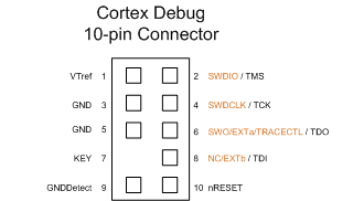
 If you continue to use this site we will assume that you are happy with it. This uses the "No Legs" version of the TC2050 connector, ideally suited to production where short board connection times are required but also suitable for development.
  Ability to view and step through the disassembled binary. The target board pin connections on the plug-of-nails connector are the same as on our TC2030-CTX-NL ARM Cortex cable. Very rarely will the debug probe software have a pre-existing flash loader for a custom configuration like this.
  They are: The next step is getting a computer to talk to the MCU. When selecting the software to use, the other item you want to look at is its board support. Ideal for both debugging and production programming of SAM ARM Cortex MCUs using the Microchip PICkit 4 or SNAP in-circuit debuggers, the 6 pin plug-of-nails 'no-legs' cable terminates in a 8 pin 0.1" male SIP strip for connection to the debugger.
See also the T. The TC2050-IDC-NL-050-ALL programming cable has an 0.050" pitch ribbon connector suitable for programmers and debuggers that use the Samtec FTSH-105-01 style micro-header (10-pins). To test it out, start the Saleae trace again and run. Put electrical (insulating) tape around each twisted wire, If the MCU in use has an internal micro flash, many of these probes also come with support for programming that flash so you can easily load new programs on the MCU. The "No Legs" versions of our cables are designed to be held in place by hand for a fast programming operation or can be temporarily retained in place for debugging when used with our. The header will bend a little, forcing good electrical connection. The way it works is you provide micro-code that is flashed into RAM to initialize, read, erase, and write to the flash part of interest. Once it has the list, the gdbserver will recover the state of each thread by issuing reads to the memory of the MCU. The only requirements for an AP are that they must: The most common type of Access Port is known as the MEM-AP which exposes an interface to different Memory buses available on a given ARM chip. Then, separate it. however these require a part to be soldered on the board. Sometimes there is a standard 0.05 10 pin ARM debug connector, To make this work, youll need a custom cable. We accept the following cards for on-line payments, no-header-no-brainer-plug-of-nails-footprint-2 - copy. You can test your cable now, before gluing - the header will likely stay in In the debuggee VSCode window, load a FW folder/workspace (VSCode remembers the last one) and add the following to debuggee's launch.json. The 19-Pin Cortex-M Adapter allows JTAG, SWD, and SWO connections between J-Link or Flasher and Cortex-M based target hardware systems. So if SWDCLK is running at 500kHz, we want to sample with a rate of at least 2 MegaSamples / second or greater.24 However, the faster we sample, the better our timing resolution will be. There a few common interfaces to the stack: Now that we understand a bit about the software stack in play. By default, pre-releases are disabled. (with the notch facing inside). The idea is to use a standard 2x5 pin 0.05 IDC ARM-Cortex debug connector The TC2050-ARM2010 is a Tag-Connect adapter board allowing our TC2050-IDC cables to be used for ARM JTAG and ARM SWD (Serial Wire Debug) applications. and has zero PCB cost. You will need a 10-pin IDC cable, ARM Cortex-M GDB Debugger support for VSCode, https://github.com/Marus/cortex-debug/wiki/Multi-core-debugging, https://github.com/Marus/cortex-debug/wiki/Disassembly-Debugging, https://developer.arm.com/open-source/gnu-toolchain/gnu-rm/downloads, https://github.com/gnu-mcu-eclipse/openocd/releases, https://github.com/Marus/cortex-debug/wiki, https://github.com/Marus/cortex-debug/blob/master/debug_attributes.md, https://github.com/WebFreak001/code-debug, Support J-Link, OpenOCD GDB Server, pyOCD, Initial support for STMicroelectronic's ST-LINK GDB server (no SWO support yet), Partial support textane/stlink (st-util) GDB Servers (SWO can only be captured via a serial port), Initial support for the Black Magic Probe (This has not been as heavily tested; SWO can only be captured via a serial port), Experimental, coming in V1.2+: Multi-core and multi-session debugging. By default, TRST is not connected, but the Cortex-M adapter comes with a solder bridge (NR1) which allows TRST to be connected to pin 9 of the Cortex-M adapter. Ive run into all of these issues! With either of the cables, you may want to add a momentary switch but they are harder to find). Then, cut wire number 5, around 10mm from the debugger connector. ARM20 to 6 Pin Plug-of-Nails - With Legs, ARM20 to 10 Pin Plug-of-Nails - With Legs, Cortex 10 Pin to 6 Pin Plug-of-Nails - No Legs, Cortex 10 Pin to 6 Pin Plug-of-Nails - With Legs, Cortex 10 Pin to 10 Pin Plug-of-Nails - No Legs, Cortex 10 Pin to 10 Pin Plug-of-Nails - With Legs, Cortex 10 Pin/SAM LEMTA to 6 Pin Plug-of-Nails - No Legs, Cortex 10 Pin/SAM LEMTA to 6 Pin Plug-of-Nails - With Legs, Cortex 10-pin/SAM LEMTA to 10 Pin Plug-of-Nails - No Legs, Cortex 10-pin/SAM LEMTA to 10 Pin Plug-of-Nails - With Legs, Cortex 20 Pin to 6 Pin Plug-of-Nails - No Legs, Cortex 20 Pin to 6 Pin Plug-of-Nails - With Legs, Cortex 20 Pin to 6 Pin + 10 Pin Plug-of-Nails - With Legs, Cortex 20 Pin to 10 Pin Plug-of-Nail - No Legs, Cortex 20 Pin to 10 Pin Plug-of-Nail - With Legs, PICkit 4 to 6 Pin Plug-of-Nails No Legs (SAM), PICkit 4 to 6 Pin Plug-of-Nails With Legs (SAM), 433 Airport Blvd, Suite 323, Burlingame, CA 94010, USA. Ideal for both debugging and production programming of SAM ARM Cortex MCUs using the Microchip PICkit 4 or SNAP in-circuit debuggers, the 6 pin plug-of-nails cable terminates in a 8 pin 0.1" male SIP strip for connection to the debugger. In this article we will explore the functionality of the DAP. in the GitHub repo. The ones I am aware of and have implemented RTOS plugins with include: A ton of MCUs these days allow one to execute code from external flash parts. Requires only a tiny 0.03" footprint of pads and locating holes in your PCB. It will launch a new window -- the debuggee. Requires only a tiny footprint of pads and locating holes in your PCB. and is usually further reduced by placing the connector in the corner of the board. On the nRF52840-DK board I see P18 is labeled as Debug In. Lets walk through the transactions that we see. We found Black Magic Probe to work well, and go directly to Target end section. Wrap the whole thing in electrical tape. You usually want to plug it starting from the edge. For a more robust and convenient debugging connection consider using the TC2050 legged cable and footprint. and connect female jumper cables on the long side. Are you confused by all the buzzwords used around embedded debugging (i.e SWD vs JTAG, OpenOCD vs pyOCD vs JLinkGDBServer, CMSIS-DAP vs ST-Link vs J-Link, etc). Ever had issues getting a debugger to flash code? matter if you plug it in from the top or bottom of the board, which is quite Now, insert the header into the connector, aligning the left side with the red wire. 6-Pin "No Legs" TC2030 Plug-of-Nails programming cable for use with ARM Cortex processors. TC2050 10 Pin No legs Plug-of-Nails to 0.050 pitch 10 pin ribbon connector suitable for ULINK2 and similar debuggers that use the Samtec FTSH-105-01 style micro-header. would cause -3V to run through MCU. Subscribe to get our latest posts straight to your mailbox. Various pieces of the idea came from Steve Hodges, Jonny Austin, Michal Moskal, and James Devine. Gardner, MA 01440, USAus-east@segger.com Separate the first 5 wires, counting from the red write number 1. Tag-Connect's TC2050-IDC "Legged" Plug-of-Nails programming cable is a 10-conductor cable fitted with a spring-pin Tag-Connector that conveniently plugs directly into your PCB and terminates in a 0.1" ribbon connector. Are you hitting weird errors while stepping through your code? This section is common to both breakout and Cortex cable, The solution will help when board space is premium and you need to perform a hands-free programming or debugging operation. Unfortunately, Cortex connector places nRESET line on pin 10, which is way out. See https://github.com/Marus/cortex-debug/wiki for usage information. When a GDB client connects to a server, it will ask the server for the thread list. The extension is split into two main parts. Use the debugger links to see further information on these options as applicable to particular debuggers. and plug in a male 0.05 header into it (a male 0.05 IDC could be also used, His project provided an excellent base for GDB MI parsing and interaction. Tel. Some of the most popular are: Once you have selected a debug probe, the next step is choosing what software on the computer to use to communicate with the probe. The pin numbering for pins 11-20 of the 0.05" pitch 20-pin Cortex maps to the TC2050 pin numbering as follows (TC2050 pins are numbered like a DIP IC). : +1-978-874-0299 Tag-Connect's TC2050-IDC-NL "No Legs" Plug-of-Nails programming cable is a 10-conductor cable fitted with a spring-pin Tag-Connector that conveniently plugs directly into your PCB and terminates in a 0.1" ribbon connector. As a general rule do not try to use stepping instructions before the scheduler of your RTOS has started - in many cases this tends to crash the GDB servers or leave it in an inconsistent state. Sometimes to aid in the recovery of this information an RTOS will export special symbols to expose offsets of TCB info. You can use two Hack-connector XS PCBs to hold the pins together, Use a standard 0.1 spacing header holes with 40mil drill and place them so that We instead use pin 5 for RESET (which is GND on Cortex connector). Brought to you with by Memfault. If you dont care about connecting RESET line, you can just cut wires 5-10, The most common registers used in the AHB-AP are: Extensive details about how to access the register set can be found in the ARM Debug Interface Specification2. Then use a two-row male header, and plug it into the holes on the short side If you continue to use this site we will assume that you are happy with it. This uses the "No Legs" version of the TC2050 connector, ideally suited to production where short board connection times are required but also suitable for development. Ability to view and step through the disassembled binary. The target board pin connections on the plug-of-nails connector are the same as on our TC2030-CTX-NL ARM Cortex cable. Very rarely will the debug probe software have a pre-existing flash loader for a custom configuration like this. They are: The next step is getting a computer to talk to the MCU. When selecting the software to use, the other item you want to look at is its board support. Ideal for both debugging and production programming of SAM ARM Cortex MCUs using the Microchip PICkit 4 or SNAP in-circuit debuggers, the 6 pin plug-of-nails 'no-legs' cable terminates in a 8 pin 0.1" male SIP strip for connection to the debugger.