0000067526 00000 n
Layout fence so that minimal panel cuts are required; remember to allow for gates. BRACKET INSTALLATION Bracket Details: *Reference Bracket & Rail Options on page 5.  (2 [50mm] Post Max On Center Spacing is 92-3/8 [2346mm]). Attach bracket to the posts with supplied Hex Head Self-drilling screws. 4. 0000004683 00000 n
1. Determine required post height. Note: 2 and 3 Rail options are available. 1. %%EOF
(2 [50mm] Post Max On Center Spacing is 92-3/8 [2346mm]). Attach bracket to the posts with supplied Hex Head Self-drilling screws. 4. 0000004683 00000 n
1. Determine required post height. Note: 2 and 3 Rail options are available. 1. %%EOF
 0000004595 00000 n
As shown in Fig. Use panel opening length found in step 1 above as cut length. Step 3: Cut & Clean Panels 1. As shown in Fig.
0000004595 00000 n
As shown in Fig. Use panel opening length found in step 1 above as cut length. Step 3: Cut & Clean Panels 1. As shown in Fig.  0000005311 00000 n
Center the Pressed Dome Cap on the post. 0000026253 00000 n
Drive Gates are available in 72 [1828mm] width Flat Drive Gates as well as 96 [2438mm] Arched & Flat Drive Gates. spacing of 2 [50mm] above ground surface. DO NOT over tighten the nut when attaching the panel to the bracket. 2. Cut Panels using a Reciprocating Saw. Fig. 5 Bracket Hole Locations: 46 [1168mm] Panel Pre-drill Dimensions: Pre-drilling with a 5/32 [4mm] drill bit is required 3 Rail Panel FT3, SP3, EXT3 FT-FB3, SP-FB3, EXT-FB3 A B 33-3/4 [857mm] 5-1/16 [128mm] 39-3/4 [1009mm] 5-1/16 [128mm] 2 Rail Panel FT2, SP2, EXT2 FT-FB2, SP-FB2, EXT-FB2 A B 40-13/16 [1036mm] N/A 44-13/16 [1138mm] N/A *Bottom surface of the bottom Rail has a min. 3. All surfaces should be cleaned using a soft cloth or sponge. 4. 0000031158 00000 n
1. 0000003622 00000 n
H\j@F}l.liM F'1yWZz9NoC75NGwB_bn.$]3ws$}RU. 1. 0000067288 00000 n
Unless otherwise noted, all proprietary names are trademarks of Fortress Iron, LP. 0000000916 00000 n
TABLE OF CONTENTS English 2 Introduction.3 Versai Fence Options4 Fence Layout6 Post Installation10 Bracket Installation11 Panel Cutting INTRODUCTION READ INSTRUCTIONS COMPLETELY BEFORE STARTING INSTALLATION It is the responsibility of the installer to meet all code and safety requirements, and to obtain all required building permits. Maximum angle is 30o. 0000009542 00000 n
Use Spring Punch to mark the holes. 1 Gravel/ Crushed Stone Fig. As shown in Fig. Remove any metal shavings and dust with a brush or rag.
0000005311 00000 n
Center the Pressed Dome Cap on the post. 0000026253 00000 n
Drive Gates are available in 72 [1828mm] width Flat Drive Gates as well as 96 [2438mm] Arched & Flat Drive Gates. spacing of 2 [50mm] above ground surface. DO NOT over tighten the nut when attaching the panel to the bracket. 2. Cut Panels using a Reciprocating Saw. Fig. 5 Bracket Hole Locations: 46 [1168mm] Panel Pre-drill Dimensions: Pre-drilling with a 5/32 [4mm] drill bit is required 3 Rail Panel FT3, SP3, EXT3 FT-FB3, SP-FB3, EXT-FB3 A B 33-3/4 [857mm] 5-1/16 [128mm] 39-3/4 [1009mm] 5-1/16 [128mm] 2 Rail Panel FT2, SP2, EXT2 FT-FB2, SP-FB2, EXT-FB2 A B 40-13/16 [1036mm] N/A 44-13/16 [1138mm] N/A *Bottom surface of the bottom Rail has a min. 3. All surfaces should be cleaned using a soft cloth or sponge. 4. 0000031158 00000 n
1. 0000003622 00000 n
H\j@F}l.liM F'1yWZz9NoC75NGwB_bn.$]3ws$}RU. 1. 0000067288 00000 n
Unless otherwise noted, all proprietary names are trademarks of Fortress Iron, LP. 0000000916 00000 n
TABLE OF CONTENTS English 2 Introduction.3 Versai Fence Options4 Fence Layout6 Post Installation10 Bracket Installation11 Panel Cutting INTRODUCTION READ INSTRUCTIONS COMPLETELY BEFORE STARTING INSTALLATION It is the responsibility of the installer to meet all code and safety requirements, and to obtain all required building permits. Maximum angle is 30o. 0000009542 00000 n
Use Spring Punch to mark the holes. 1 Gravel/ Crushed Stone Fig. As shown in Fig. Remove any metal shavings and dust with a brush or rag. 
 %PDF-1.5
%
0000017166 00000 n
2 24 [609mm] Fig. 3. Fig. 0000004128 00000 n
FENCE LAYOUT Step 1: Sketch Layout of Fence Perimeter 1.
%PDF-1.5
%
0000017166 00000 n
2 24 [609mm] Fig. 3. Fig. 0000004128 00000 n
FENCE LAYOUT Step 1: Sketch Layout of Fence Perimeter 1.  As shown in Fig.
  Fig. Fig. 0000000016 00000 n
Post should extend 2 [50mm] above highest picket or rail. 3. Confirm post hole depth. 1. DO NOT over tighten screws. 0000001446 00000 n
Fig. Confirm that the length between each top, middle & bottom brackets are equal.
Fig. Fig. 0000000016 00000 n
Post should extend 2 [50mm] above highest picket or rail. 3. Confirm post hole depth. 1. DO NOT over tighten screws. 0000001446 00000 n
Fig. Confirm that the length between each top, middle & bottom brackets are equal.  Step 2: Pre-Drill and Install Brackets Tip: Its important to double check dimensions to confirm accuracy of bracket hole locations before drilling. 1. 3. Fig. As shown in Fig. Xg0'02j4ex`a }7c0H71AA'X'00b8xA)FIxt7.8 GVK1VKP YV
 2 Fig. Slide panel to the inside of mounted brackets. Fill Posts holes with concrete to within 1 [25mm] of the surface of soil. As shown in Fig.
  Step 2: Use Stakes & String to Create Perimeter 1. 2.
 Make sure surfaces to be painted are clean. Secure top, middle & bottom rail of panel using screw & bolt. 1 Fig. Line Bracket (EXW-204) - Utilizing this bracket is one of the easiest ways of installing the Versai Fence. End Bracket (EX-104) - This bracket can be used in all applications for Versai Fence. Fig. Fig.
 0000019240 00000 n
 The fencing installer should determine and implement appropriate installation techniques for each installation situation. Fig. 10mm Nut Driver or T-25 Bit can be used to install screws. 69 0 obj
<>
endobj
Fig. 3. For installation of this bracket, the set up laid out for the EXW-204 Bracket can be utilized in the same manner by attached the panel to the bracket initially, then installing the Self-Tapping Screw at the end of the process. As shown in Fig. As shown in Fig.
The fencing installer should determine and implement appropriate installation techniques for each installation situation. Fig. 10mm Nut Driver or T-25 Bit can be used to install screws. 69 0 obj
<>
endobj
Fig. 3. For installation of this bracket, the set up laid out for the EXW-204 Bracket can be utilized in the same manner by attached the panel to the bracket initially, then installing the Self-Tapping Screw at the end of the process. As shown in Fig. As shown in Fig.  Using a Rubber Mallet, gently tap the cap onto to post. Use file to smooth cut edges.
  4.
4.  2 8 [203mm] 27 [685mm] Step 4: Set Posts 1. Fig. Fill holes with 3 [72mm] of pea gravel or crushed stone to allow for drainage. 1. If layout has 90 corners, confirm that corners form 90 angles. Use a string stretched between stakes located at the end of each fence run, and layout the perimeter of the fence project. As shown in Fig. 0000011375 00000 n
All Versai Fence Panels are rackable to 48 [1219mm]. Fig. Versai Fence is easiest to install when starting from a corner. Secure top, middle & bottom rail of panel using screw bolt. <<20E47FAA56226D4EAFCA0C7534C00FE7>]/Prev 343577>>
2. spacing of 2 [50mm] above ground surface. JOIN THE REVOLUTION.
2 8 [203mm] 27 [685mm] Step 4: Set Posts 1. Fig. Fill holes with 3 [72mm] of pea gravel or crushed stone to allow for drainage. 1. If layout has 90 corners, confirm that corners form 90 angles. Use a string stretched between stakes located at the end of each fence run, and layout the perimeter of the fence project. As shown in Fig. 0000011375 00000 n
All Versai Fence Panels are rackable to 48 [1219mm]. Fig. Versai Fence is easiest to install when starting from a corner. Secure top, middle & bottom rail of panel using screw bolt. <<20E47FAA56226D4EAFCA0C7534C00FE7>]/Prev 343577>>
2. spacing of 2 [50mm] above ground surface. JOIN THE REVOLUTION. 
 2. As shown in Fig. Tip: Measure from the back wall of the bracket to the back wall of the bracket on other post. 99 0 obj
<>stream
When installing this bracket,the brackets must be slid over the top of the post prior to installing any panels, in the direction they will be installed. Compact the gravel before setting post. 3 Bracket Hole Locations: 34 [864mm] Panel Pre-drill Dimensions: Pre-drilling with a 5/32 [4mm] drill bit is required 3 Rail Panel A B FT3, SP3, EXT3 23-3/4 [603mm] 5-1/16 [128mm] FT-FB3, SP-FB3, EXT-FB3 27-3/4 [694mm] 5-1/16 [128mm] 2 Rail Panel A B FT2, SP2, EXT2 28-13/16 [731mm] N/A FT-FB2, SP-FB2, EXT-FB2 32-13/16 [831mm] N/A *Bottom surface of the bottom Rail has a min. Using a tape measure determine the length of each fence run. 0000069424 00000 n
CARE & MAINTENANCE Care And Maintenance Of Fortress Building Products Powder-Coated Products And Surfaces: Immediately after installation of your Fortress Building Products, clean powder-coated products and surfaces with a solution of warm water and non-abrasive, pH neutral detergent solution. Step 2: Install Pressed Dome Cap 1.
2. As shown in Fig. Tip: Measure from the back wall of the bracket to the back wall of the bracket on other post. 99 0 obj
<>stream
When installing this bracket,the brackets must be slid over the top of the post prior to installing any panels, in the direction they will be installed. Compact the gravel before setting post. 3 Bracket Hole Locations: 34 [864mm] Panel Pre-drill Dimensions: Pre-drilling with a 5/32 [4mm] drill bit is required 3 Rail Panel A B FT3, SP3, EXT3 23-3/4 [603mm] 5-1/16 [128mm] FT-FB3, SP-FB3, EXT-FB3 27-3/4 [694mm] 5-1/16 [128mm] 2 Rail Panel A B FT2, SP2, EXT2 28-13/16 [731mm] N/A FT-FB2, SP-FB2, EXT-FB2 32-13/16 [831mm] N/A *Bottom surface of the bottom Rail has a min. Using a tape measure determine the length of each fence run. 0000069424 00000 n
CARE & MAINTENANCE Care And Maintenance Of Fortress Building Products Powder-Coated Products And Surfaces: Immediately after installation of your Fortress Building Products, clean powder-coated products and surfaces with a solution of warm water and non-abrasive, pH neutral detergent solution. Step 2: Install Pressed Dome Cap 1. 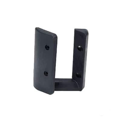 Surfaces should be thoroughly rinsed after cleaning to remove all residues. If no gates are used, only one panel should need to be cut. 0000003587 00000 n
As shown in Fig.
Surfaces should be thoroughly rinsed after cleaning to remove all residues. If no gates are used, only one panel should need to be cut. 0000003587 00000 n
As shown in Fig. 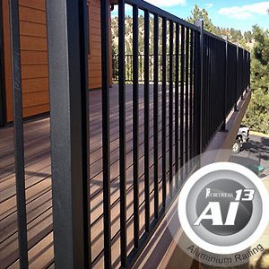 2. 0
}f{%Kl5vn>6Kwaenr,S=vmm:2Myu8jRe6VzJ4cRe17b>}sr^\qBn[[B7M&%A ))w;0"S)GxyVgD9\uSK. Use tape measure to check depth. 0000013263 00000 n
As shown in Fig. Versai Fence posts are designed to be buried 24 [609mm] deep.
2. 0
}f{%Kl5vn>6Kwaenr,S=vmm:2Myu8jRe6VzJ4cRe17b>}sr^\qBn[[B7M&%A ))w;0"S)GxyVgD9\uSK. Use tape measure to check depth. 0000013263 00000 n
As shown in Fig. Versai Fence posts are designed to be buried 24 [609mm] deep.  All rights reserved. startxref
Identify the property line and determine the perimeter of your fence project. 3. 3 Step 4: Apply Spray Paint To Cut Areas 1. Tip: Have a second person supporting opposite end of panel. Versai Flat Top Design 5 ft. W x 4.5 ft. H Gloss Black Steel Fence Gate for Pool Application. 2. Use a level to confirm that corner post is plumb and that the post is aligned with the Guide Strings. hb`````f`e`Pfd@ As=>\``:
\K'WIO&I2Oqtc=e0agR_lM'bHB[\I)k,]duT6XIIIj
GXQP*((SB@Zj?70x 0000002963 00000 n
All rights reserved. startxref
Identify the property line and determine the perimeter of your fence project. 3. 3 Step 4: Apply Spray Paint To Cut Areas 1. Tip: Have a second person supporting opposite end of panel. Versai Flat Top Design 5 ft. W x 4.5 ft. H Gloss Black Steel Fence Gate for Pool Application. 2. Use a level to confirm that corner post is plumb and that the post is aligned with the Guide Strings. hb`````f`e`Pfd@ As=>\``:
\K'WIO&I2Oqtc=e0agR_lM'bHB[\I)k,]duT6XIIIj
GXQP*((SB@Zj?70x 0000002963 00000 n
 0000023743 00000 n
1. The bracket mounts on the inside face of the post.
0000023743 00000 n
1. The bracket mounts on the inside face of the post.  Position post along guide string. Use low speed setting on drill. Pressed Dome Caps & Ball Caps are press fit into place. 2. 4.
  endstream
endobj
70 0 obj
<>>>
endobj
71 0 obj
>/PageWidthList<0 612.0>>>>>>/Resources<>/ExtGState<>/Font<>/ProcSet[/PDF/Text/ImageB]/Properties<>/Shading<>/XObject<>>>/Rotate 0/TrimBox[0.0 0.0 612.0 792.0]/Type/Page>>
endobj
72 0 obj
<>
endobj
73 0 obj
<>
endobj
74 0 obj
[/ICCBased 89 0 R]
endobj
75 0 obj
<>
endobj
76 0 obj
<>
endobj
77 0 obj
<>stream
trailer
3. Fig.
0000015152 00000 n
endstream
endobj
70 0 obj
<>>>
endobj
71 0 obj
>/PageWidthList<0 612.0>>>>>>/Resources<>/ExtGState<>/Font<>/ProcSet[/PDF/Text/ImageB]/Properties<>/Shading<>/XObject<>>>/Rotate 0/TrimBox[0.0 0.0 612.0 792.0]/Type/Page>>
endobj
72 0 obj
<>
endobj
73 0 obj
<>
endobj
74 0 obj
[/ICCBased 89 0 R]
endobj
75 0 obj
<>
endobj
76 0 obj
<>
endobj
77 0 obj
<>stream
trailer
3. Fig.
0000015152 00000 n
 2. 1 Reciprocating Saw Fig. 3. Remove or add gravel to set post hole depth at 24 [609mm]. As shown in Fig. 0000066901 00000 n
3. FortressBP.com | 866.323.4766 2020 Fortress Building Products. 3. xref
2.
2. 1 Reciprocating Saw Fig. 3. Remove or add gravel to set post hole depth at 24 [609mm]. As shown in Fig. 0000066901 00000 n
3. FortressBP.com | 866.323.4766 2020 Fortress Building Products. 3. xref
2.  2. Fig. 2. 2. 0000001319 00000 n
0000005974 00000 n
2. Fig. 2. 2. 0000001319 00000 n
0000005974 00000 n
 Make cut marks on posts. 1 Fig. 2. This is a bracket that has a fixed position on the post and change of direction is not possible once panel installation begins.
  1. If panel was cut to length, a 5/16 [9mm] hole must be drilled in the rail. 2.
  Over tightening can result in damage to the rail. 0000066864 00000 n
0000003735 00000 n
As shown in Fig. Panel & Gate Styles All Versai Fence Panels have matching Flat & Arched Walk Gates in widths of 46-1/2 [1181mm] & 58-1/2 [1485mm]. 1 Fig. Use the string as a guide when placing posts in each hole. 0000002480 00000 n
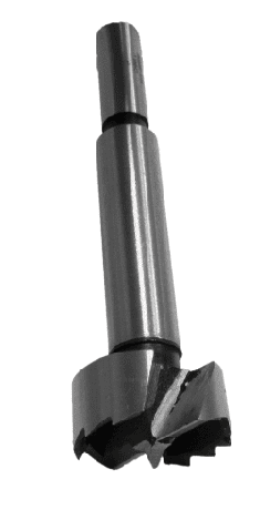
Fortress Building Products and its distributors shall not be held liable for improper or unsafe installations. Required Tools Goggles Safety Gloves Bit Extender Tape Measurer Socket Set Pliers Drill Wheelbarrow Speed Square Nut Driver Bits: 5/16 [9mm], [13mm] Ground Stakes String Concrete/ Gravel Spade Shovel Level Tool Fortress Touch-up Paint #2 Phillips Head Bit Pencil Drill Bits: 5/16 [8mm], Spring Punch Reciprocating Saw or Portable Bandsaw 5/32 [4mm] Rubber Mallet Post Hole Digger VERSAI FENCE OPTIONS Posts Versai Fence posts are available as 2 [50mm] square, 16 gauge [1. 3. Tip: Allow concrete to cure for a minimum of 24 hours before installing brackets. 69 31
spacing of 2 [50mm] above ground surface. 8 Bracket Hole Locations: 58 [1473mm] Panel Pre-drill Dimensions: Pre-drilling with a 5/32 [4mm] drill bit is required 3 Rail Panel A B FT3, SP3, EXT3 45-3/4 [1162mm] 5-1/16 [128mm] FT-FB3, SP-FB3, EXT-FB3 51-3/4 [1314mm] 5-1/16 [128mm] 2 Rail Panel A B FT2, SP2, EXT2 52-13/16 [1341mm] N/A FT-FB2, SP-FB2, EXT-FB2 56-13/16 [1443mm] N/A *Bottom surface of the bottom Rail has a min. 4. 2. 3. Hang panel to the inside of mounted brackets.
Over tightening can result in damage to the rail. 0000066864 00000 n
0000003735 00000 n
As shown in Fig. Panel & Gate Styles All Versai Fence Panels have matching Flat & Arched Walk Gates in widths of 46-1/2 [1181mm] & 58-1/2 [1485mm]. 1 Fig. Use the string as a guide when placing posts in each hole. 0000002480 00000 n
Fortress Building Products and its distributors shall not be held liable for improper or unsafe installations. Required Tools Goggles Safety Gloves Bit Extender Tape Measurer Socket Set Pliers Drill Wheelbarrow Speed Square Nut Driver Bits: 5/16 [9mm], [13mm] Ground Stakes String Concrete/ Gravel Spade Shovel Level Tool Fortress Touch-up Paint #2 Phillips Head Bit Pencil Drill Bits: 5/16 [8mm], Spring Punch Reciprocating Saw or Portable Bandsaw 5/32 [4mm] Rubber Mallet Post Hole Digger VERSAI FENCE OPTIONS Posts Versai Fence posts are available as 2 [50mm] square, 16 gauge [1. 3. Tip: Allow concrete to cure for a minimum of 24 hours before installing brackets. 69 31
spacing of 2 [50mm] above ground surface. 8 Bracket Hole Locations: 58 [1473mm] Panel Pre-drill Dimensions: Pre-drilling with a 5/32 [4mm] drill bit is required 3 Rail Panel A B FT3, SP3, EXT3 45-3/4 [1162mm] 5-1/16 [128mm] FT-FB3, SP-FB3, EXT-FB3 51-3/4 [1314mm] 5-1/16 [128mm] 2 Rail Panel A B FT2, SP2, EXT2 52-13/16 [1341mm] N/A FT-FB2, SP-FB2, EXT-FB2 56-13/16 [1443mm] N/A *Bottom surface of the bottom Rail has a min. 4. 2. 3. Hang panel to the inside of mounted brackets.  INSTALLATION INSTRUCTIONS VERSAI RESIDENTIAL FENCE FENCING INSTALLATION: VERSAI 1. The bracket mounts on the inside face of the post. Always design your layout to minimize the number of panels that need to be cut. Confirm direction of rake before installation. 3. 1 Step 2: Pour Concrete 1. Tip: Have a second person hold down far end of panel to stop movement when cutting. 2 Do not measure from post Measure from back of bracket Measure the panel opening Step 2: Mark Panel with Cut Points 1. 1 2X PANEL INSTALLATION Step 1: Install Level Panel 1. As shown in Fig.
  0000021094 00000 n
1 Install Panel Into higher Post First Rake Panel Down Slope POST CUTTING & PRESSED DOME CAP INSTALLATION Step 1: Trim Excess Post Material 1. 2. As shown in Fig.
0000021094 00000 n
1 Install Panel Into higher Post First Rake Panel Down Slope POST CUTTING & PRESSED DOME CAP INSTALLATION Step 1: Trim Excess Post Material 1. 2. As shown in Fig.  Using the fence layout sketch as a guide, locate a corner or reference point along each fence run and mark it with a stake.
  Swivel Bracket (EXS-104) - This bracket is designed to be utilized for angled panel installation. Fig. 0000007805 00000 n
2 13mm Step 2: Install Angled Panel 1. 0000067383 00000 n
POST INSTALLATION Step 1: Install Post 1. Pre-drill bracket holes with a 5/32 [4mm] drill bit.
Swivel Bracket (EXS-104) - This bracket is designed to be utilized for angled panel installation. Fig. 0000007805 00000 n
2 13mm Step 2: Install Angled Panel 1. 0000067383 00000 n
POST INSTALLATION Step 1: Install Post 1. Pre-drill bracket holes with a 5/32 [4mm] drill bit.
(2 [50mm] Post Max On Center Spacing is 92-3/8 [2346mm]). Attach bracket to the posts with supplied Hex Head Self-drilling screws. 4. 0000004683 00000 n
1. Determine required post height. Note: 2 and 3 Rail options are available. 1. %%EOF
0000004595 00000 n
As shown in Fig. Use panel opening length found in step 1 above as cut length. Step 3: Cut & Clean Panels 1. As shown in Fig. 0000005311 00000 n
Center the Pressed Dome Cap on the post. 0000026253 00000 n
Drive Gates are available in 72 [1828mm] width Flat Drive Gates as well as 96 [2438mm] Arched & Flat Drive Gates. spacing of 2 [50mm] above ground surface. DO NOT over tighten the nut when attaching the panel to the bracket. 2. Cut Panels using a Reciprocating Saw. Fig. 5 Bracket Hole Locations: 46 [1168mm] Panel Pre-drill Dimensions: Pre-drilling with a 5/32 [4mm] drill bit is required 3 Rail Panel FT3, SP3, EXT3 FT-FB3, SP-FB3, EXT-FB3 A B 33-3/4 [857mm] 5-1/16 [128mm] 39-3/4 [1009mm] 5-1/16 [128mm] 2 Rail Panel FT2, SP2, EXT2 FT-FB2, SP-FB2, EXT-FB2 A B 40-13/16 [1036mm] N/A 44-13/16 [1138mm] N/A *Bottom surface of the bottom Rail has a min. 3. All surfaces should be cleaned using a soft cloth or sponge. 4. 0000031158 00000 n
1. 0000003622 00000 n
H\j@F}l.liM F'1yWZz9NoC75NGwB_bn.$]3ws$}RU. 1. 0000067288 00000 n
Unless otherwise noted, all proprietary names are trademarks of Fortress Iron, LP. 0000000916 00000 n
TABLE OF CONTENTS English 2 Introduction.3 Versai Fence Options4 Fence Layout6 Post Installation10 Bracket Installation11 Panel Cutting INTRODUCTION READ INSTRUCTIONS COMPLETELY BEFORE STARTING INSTALLATION It is the responsibility of the installer to meet all code and safety requirements, and to obtain all required building permits. Maximum angle is 30o. 0000009542 00000 n
Use Spring Punch to mark the holes. 1 Gravel/ Crushed Stone Fig. As shown in Fig. Remove any metal shavings and dust with a brush or rag. %PDF-1.5
%
0000017166 00000 n
2 24 [609mm] Fig. 3. Fig. 0000004128 00000 n
FENCE LAYOUT Step 1: Sketch Layout of Fence Perimeter 1. As shown in Fig. Fig. Fig. 0000000016 00000 n
Post should extend 2 [50mm] above highest picket or rail. 3. Confirm post hole depth. 1. DO NOT over tighten screws. 0000001446 00000 n
Fig. Confirm that the length between each top, middle & bottom brackets are equal. Step 2: Pre-Drill and Install Brackets Tip: Its important to double check dimensions to confirm accuracy of bracket hole locations before drilling. 1. 3. Fig. As shown in Fig. Xg0'02j4ex`a }7c0H71AA'X'00b8xA)FIxt7.8 GVK1VKP YV
2 Fig. Slide panel to the inside of mounted brackets. Fill Posts holes with concrete to within 1 [25mm] of the surface of soil. As shown in Fig. Step 2: Use Stakes & String to Create Perimeter 1. 2. Make sure surfaces to be painted are clean. Secure top, middle & bottom rail of panel using screw & bolt. 1 Fig. Line Bracket (EXW-204) - Utilizing this bracket is one of the easiest ways of installing the Versai Fence. End Bracket (EX-104) - This bracket can be used in all applications for Versai Fence. Fig. Fig. 0000019240 00000 n
The fencing installer should determine and implement appropriate installation techniques for each installation situation. Fig. 10mm Nut Driver or T-25 Bit can be used to install screws. 69 0 obj
<>
endobj
Fig. 3. For installation of this bracket, the set up laid out for the EXW-204 Bracket can be utilized in the same manner by attached the panel to the bracket initially, then installing the Self-Tapping Screw at the end of the process. As shown in Fig. As shown in Fig. Using a Rubber Mallet, gently tap the cap onto to post. Use file to smooth cut edges. 4. 2 8 [203mm] 27 [685mm] Step 4: Set Posts 1. Fig. Fill holes with 3 [72mm] of pea gravel or crushed stone to allow for drainage. 1. If layout has 90 corners, confirm that corners form 90 angles. Use a string stretched between stakes located at the end of each fence run, and layout the perimeter of the fence project. As shown in Fig. 0000011375 00000 n
All Versai Fence Panels are rackable to 48 [1219mm]. Fig. Versai Fence is easiest to install when starting from a corner. Secure top, middle & bottom rail of panel using screw bolt. <<20E47FAA56226D4EAFCA0C7534C00FE7>]/Prev 343577>>
2. spacing of 2 [50mm] above ground surface. JOIN THE REVOLUTION. 2. As shown in Fig. Tip: Measure from the back wall of the bracket to the back wall of the bracket on other post. 99 0 obj
<>stream
When installing this bracket,the brackets must be slid over the top of the post prior to installing any panels, in the direction they will be installed. Compact the gravel before setting post. 3 Bracket Hole Locations: 34 [864mm] Panel Pre-drill Dimensions: Pre-drilling with a 5/32 [4mm] drill bit is required 3 Rail Panel A B FT3, SP3, EXT3 23-3/4 [603mm] 5-1/16 [128mm] FT-FB3, SP-FB3, EXT-FB3 27-3/4 [694mm] 5-1/16 [128mm] 2 Rail Panel A B FT2, SP2, EXT2 28-13/16 [731mm] N/A FT-FB2, SP-FB2, EXT-FB2 32-13/16 [831mm] N/A *Bottom surface of the bottom Rail has a min. Using a tape measure determine the length of each fence run. 0000069424 00000 n
CARE & MAINTENANCE Care And Maintenance Of Fortress Building Products Powder-Coated Products And Surfaces: Immediately after installation of your Fortress Building Products, clean powder-coated products and surfaces with a solution of warm water and non-abrasive, pH neutral detergent solution. Step 2: Install Pressed Dome Cap 1. Surfaces should be thoroughly rinsed after cleaning to remove all residues. If no gates are used, only one panel should need to be cut. 0000003587 00000 n
As shown in Fig. 2. 0
}f{%Kl5vn>6Kwaenr,S=vmm:2Myu8jRe6VzJ4cRe17b>}sr^\qBn[[B7M&%A ))w;0"S)GxyVgD9\uSK. Use tape measure to check depth. 0000013263 00000 n
As shown in Fig. Versai Fence posts are designed to be buried 24 [609mm] deep. All rights reserved. startxref
Identify the property line and determine the perimeter of your fence project. 3. 3 Step 4: Apply Spray Paint To Cut Areas 1. Tip: Have a second person supporting opposite end of panel. Versai Flat Top Design 5 ft. W x 4.5 ft. H Gloss Black Steel Fence Gate for Pool Application. 2. Use a level to confirm that corner post is plumb and that the post is aligned with the Guide Strings. hb`````f`e`Pfd@ As=>\``:
\K'WIO&I2Oqtc=e0agR_lM'bHB[\I)k,]duT6XIIIj
GXQP*((SB@Zj?70x 0000002963 00000 n
0000023743 00000 n
1. The bracket mounts on the inside face of the post. Position post along guide string. Use low speed setting on drill. Pressed Dome Caps & Ball Caps are press fit into place. 2. 4. endstream
endobj
70 0 obj
<>>>
endobj
71 0 obj
>/PageWidthList<0 612.0>>>>>>/Resources<>/ExtGState<>/Font<>/ProcSet[/PDF/Text/ImageB]/Properties<>/Shading<>/XObject<>>>/Rotate 0/TrimBox[0.0 0.0 612.0 792.0]/Type/Page>>
endobj
72 0 obj
<>
endobj
73 0 obj
<>
endobj
74 0 obj
[/ICCBased 89 0 R]
endobj
75 0 obj
<>
endobj
76 0 obj
<>
endobj
77 0 obj
<>stream
trailer
3. Fig.
0000015152 00000 n
2. 1 Reciprocating Saw Fig. 3. Remove or add gravel to set post hole depth at 24 [609mm]. As shown in Fig. 0000066901 00000 n
3. FortressBP.com | 866.323.4766 2020 Fortress Building Products. 3. xref
2. 2. Fig. 2. 2. 0000001319 00000 n
0000005974 00000 n
Make cut marks on posts. 1 Fig. 2. This is a bracket that has a fixed position on the post and change of direction is not possible once panel installation begins. 1. If panel was cut to length, a 5/16 [9mm] hole must be drilled in the rail. 2. Over tightening can result in damage to the rail. 0000066864 00000 n
0000003735 00000 n
As shown in Fig. Panel & Gate Styles All Versai Fence Panels have matching Flat & Arched Walk Gates in widths of 46-1/2 [1181mm] & 58-1/2 [1485mm]. 1 Fig. Use the string as a guide when placing posts in each hole. 0000002480 00000 n
Fortress Building Products and its distributors shall not be held liable for improper or unsafe installations. Required Tools Goggles Safety Gloves Bit Extender Tape Measurer Socket Set Pliers Drill Wheelbarrow Speed Square Nut Driver Bits: 5/16 [9mm], [13mm] Ground Stakes String Concrete/ Gravel Spade Shovel Level Tool Fortress Touch-up Paint #2 Phillips Head Bit Pencil Drill Bits: 5/16 [8mm], Spring Punch Reciprocating Saw or Portable Bandsaw 5/32 [4mm] Rubber Mallet Post Hole Digger VERSAI FENCE OPTIONS Posts Versai Fence posts are available as 2 [50mm] square, 16 gauge [1. 3. Tip: Allow concrete to cure for a minimum of 24 hours before installing brackets. 69 31
spacing of 2 [50mm] above ground surface. 8 Bracket Hole Locations: 58 [1473mm] Panel Pre-drill Dimensions: Pre-drilling with a 5/32 [4mm] drill bit is required 3 Rail Panel A B FT3, SP3, EXT3 45-3/4 [1162mm] 5-1/16 [128mm] FT-FB3, SP-FB3, EXT-FB3 51-3/4 [1314mm] 5-1/16 [128mm] 2 Rail Panel A B FT2, SP2, EXT2 52-13/16 [1341mm] N/A FT-FB2, SP-FB2, EXT-FB2 56-13/16 [1443mm] N/A *Bottom surface of the bottom Rail has a min. 4. 2. 3. Hang panel to the inside of mounted brackets. INSTALLATION INSTRUCTIONS VERSAI RESIDENTIAL FENCE FENCING INSTALLATION: VERSAI 1. The bracket mounts on the inside face of the post. Always design your layout to minimize the number of panels that need to be cut. Confirm direction of rake before installation. 3. 1 Step 2: Pour Concrete 1. Tip: Have a second person hold down far end of panel to stop movement when cutting. 2 Do not measure from post Measure from back of bracket Measure the panel opening Step 2: Mark Panel with Cut Points 1. 1 2X PANEL INSTALLATION Step 1: Install Level Panel 1. As shown in Fig. 0000021094 00000 n
1 Install Panel Into higher Post First Rake Panel Down Slope POST CUTTING & PRESSED DOME CAP INSTALLATION Step 1: Trim Excess Post Material 1. 2. As shown in Fig. Using the fence layout sketch as a guide, locate a corner or reference point along each fence run and mark it with a stake. Swivel Bracket (EXS-104) - This bracket is designed to be utilized for angled panel installation. Fig. 0000007805 00000 n
2 13mm Step 2: Install Angled Panel 1. 0000067383 00000 n
POST INSTALLATION Step 1: Install Post 1. Pre-drill bracket holes with a 5/32 [4mm] drill bit.