Then select the trap connection size to meet the installation requirements. Some traps have a slightly larger discharge capacity because condensate can also be discharged through their thermostatic air vent. Now, Ill go to a capacity chart and this happens to be a mechanical steam trap capacity chart. 
 By submitting this form, you consent to receiving marketing communications from Inveno Engineering. The sizing factor for: Inverted buckets: Three to One. This test-and-replace strategy is subject to two main costs by the owner: testing and steam loss. Table 1provides the recommended steam trap to use based on the location and function within typical heating and process systems. The most common type of thermodynamic trap is a disc type where the disc is the only moving part. Air limits piping systems ability to carry their full capacity of steam and acts as an insulating agent within heat transfer devices. All working components can be replaced with the trap body remaining in-line. A failed oversized trap has a larger orifice opening that can potentially blow through larger quantities of steam and waste more energy. The worst-case scenario would assume the entire orifice is open, but typically condensate simultaneously flows through the trap so approximately 1/3 to 1/2 of the orifice will contain lost steam, according to the DOE. This bypassed steam provides no useful heating value to the system and effectively reduces the overall capacity of the system or requires additional capacity to make up for the system losses to meet the demand of the building. 0000002549 00000 n
0000006695 00000 n
., The GP14 Power Trap (photo) is an advanced condensate-recovery system for pumping high-temperature condensate for vented receivers, sumps and other, Testing steam-trap stations can be very easy if the plant provides the correct equipment, training and commitment to the steam-system, Steam often provides the majority of heat, but its quality is not always carefully managed. The other one for mechanical, is the inverted buckets and it works the same way as we were talking about the other application was flow and thermostatic and you have a differential pressure up here of 50 psi, you would go down to the chart, til you find something 2000 pounds per hour and make your selection of the orifices that are there. Steam traps in HVAC applications are generally found in two locations: drip traps and at process equipment. We have a 50-psi differential across a steam trap. This pulls the disc off the seat allowing condensate to be discharged through the seat orifice located at the top of the trap. Piping in condensate systems is recommended to be schedule 80 steel piping in most cases, due to heavier wall thicknesses to extend the life of the pipe. The operating pressure to the process as you can see is at 75 psi. The PDF document will be sent to the email address specified. Failed steam traps can have a spiraling cost impact above and beyond wasted steam, including increased feedwater costs, additional chemical treatment and make-up water, and higher blowdown requirements. 0000003351 00000 n
s%zD%*ll7wUX)
(Ca
[Bm],f:W. Implement a Sustainable Steam Trap Management Program, Impact Plant Performance by Improving the Steam System, Water Hammer: In Steam Distribution Lines, Water Hammer: In Condensate Transport Piping, Identifying Water Hammer Using a Thermal Camera, Mitigation of Water Hammer in Vertical Flashing Condensate Transport Piping. Steam Trap Management: Do Something; Anything. Examples of thermostatic steam traps include bi-metal and bellows type steam traps.
By submitting this form, you consent to receiving marketing communications from Inveno Engineering. The sizing factor for: Inverted buckets: Three to One. This test-and-replace strategy is subject to two main costs by the owner: testing and steam loss. Table 1provides the recommended steam trap to use based on the location and function within typical heating and process systems. The most common type of thermodynamic trap is a disc type where the disc is the only moving part. Air limits piping systems ability to carry their full capacity of steam and acts as an insulating agent within heat transfer devices. All working components can be replaced with the trap body remaining in-line. A failed oversized trap has a larger orifice opening that can potentially blow through larger quantities of steam and waste more energy. The worst-case scenario would assume the entire orifice is open, but typically condensate simultaneously flows through the trap so approximately 1/3 to 1/2 of the orifice will contain lost steam, according to the DOE. This bypassed steam provides no useful heating value to the system and effectively reduces the overall capacity of the system or requires additional capacity to make up for the system losses to meet the demand of the building. 0000002549 00000 n
0000006695 00000 n
., The GP14 Power Trap (photo) is an advanced condensate-recovery system for pumping high-temperature condensate for vented receivers, sumps and other, Testing steam-trap stations can be very easy if the plant provides the correct equipment, training and commitment to the steam-system, Steam often provides the majority of heat, but its quality is not always carefully managed. The other one for mechanical, is the inverted buckets and it works the same way as we were talking about the other application was flow and thermostatic and you have a differential pressure up here of 50 psi, you would go down to the chart, til you find something 2000 pounds per hour and make your selection of the orifices that are there. Steam traps in HVAC applications are generally found in two locations: drip traps and at process equipment. We have a 50-psi differential across a steam trap. This pulls the disc off the seat allowing condensate to be discharged through the seat orifice located at the top of the trap. Piping in condensate systems is recommended to be schedule 80 steel piping in most cases, due to heavier wall thicknesses to extend the life of the pipe. The operating pressure to the process as you can see is at 75 psi. The PDF document will be sent to the email address specified. Failed steam traps can have a spiraling cost impact above and beyond wasted steam, including increased feedwater costs, additional chemical treatment and make-up water, and higher blowdown requirements. 0000003351 00000 n
s%zD%*ll7wUX)
(Ca
[Bm],f:W. Implement a Sustainable Steam Trap Management Program, Impact Plant Performance by Improving the Steam System, Water Hammer: In Steam Distribution Lines, Water Hammer: In Condensate Transport Piping, Identifying Water Hammer Using a Thermal Camera, Mitigation of Water Hammer in Vertical Flashing Condensate Transport Piping. Steam Trap Management: Do Something; Anything. Examples of thermostatic steam traps include bi-metal and bellows type steam traps.  Here are some tips on, The new IBV range of high-pressure inverted-bucket steam traps (photo) are available in sizes from to 3 in. of Energy (DOE), approximately 20% of steam leaving a boiler plant could be lost due to leaking steam traps in steam systems without a preventative maintenance program. Test methods to determine steam trap operation can be segmented into four categories: visual, ultrasonic, temperature, and conductivity. At the inlet to the steam trap, a strainer with a blowdown valve will provide the ability to remove any scale, dirt, and debris in the piping system and allow an operator to depressurize the steam trap for maintenance.
  To get the most accurate diagnosis, maintenance personnel should integrate conductivity readings with temperature. Going back to our example, again, is that we have 75 psi to the inlet of this valve, it doesnt mean we have 75 psi down here. Now, we determine the orifice size for the following data required. Print
  All rights reserved. Intentional back pressure is the design of the system and a lot of systems we will run under pressure. Check Valve (suffix CV) Built-in Inlet Check Valve is recommended when used on Superheated Steam
By David Grassl, PE, Ring & DuChateau LLP, Milwaukee, By using this website, you agree to our use of cookies.
All rights reserved. Intentional back pressure is the design of the system and a lot of systems we will run under pressure. Check Valve (suffix CV) Built-in Inlet Check Valve is recommended when used on Superheated Steam
By David Grassl, PE, Ring & DuChateau LLP, Milwaukee, By using this website, you agree to our use of cookies.  When steam enters, it fills the inverted bucket causing the bucket to float to the surface which closes the discharge valve, containing the steam in
0000006886 00000 n
When steam enters, it fills the inverted bucket causing the bucket to float to the surface which closes the discharge valve, containing the steam in
0000006886 00000 n
 Steam traps should generally be sized two to three times the amount of condensate that will be produced under normal operation to account for varying pressures and condensate loads. 0000003839 00000 n
Drip traps consist of a short piece of vertical pipe called a drip leg on the bottom of the steam main with a steam trap. Flash steam is created when condensate flashes to vapor upon expansion to atmospheric pressure and is typically a billowing plume, compared to live steam which is a sharper, higher velocity plume that may not be immediately visible as it exits the test valve, according to the DOE. Many factors influence the success of a steam and condensate system. Devices on the market today are able to compare the sound of a known condition to the tested trap to accurately determine if the trap is functional or blowing steam. Size/Model: IB1031, 80 PSIG, Specify pipe size (1/2, 3/4), or IB1041, 80 PSIG, Specify pipe size (3/4, 1), How to Order Accessories:
Learn to estimate the amounts of energy and money wasted from a blown steam trap. 272 0 obj
<<
/Linearized 1
/O 276
/H [ 1494 881 ]
/L 1148579
/E 17121
/N 35
/T 1143020
>>
endobj
xref
272 40
0000000016 00000 n
Comment Visual indication requires that the personnel observing the visual cues be knowledgeable enough to determine the condition of the steam trap as blow-through steam and flash steam can both escape the test connection with only one indicating a failure. Drip traps are located as part of the main steam distribution piping as the system radiates heat, loses energy, and creates condensate within the piping system. Visual: Visual testing involves a test valve arrangement or inline sight glass to visually determine if the steam trap is malfunctioning. At the bottom of the drip leg, a drain valve should be provided to remove condensate, and isolation valves and unions are recommended at the inlet and outlet of the steam trap to simplify trap removal. For example, the orifice diameters available for the J3X Free Float steam trap are only approx. Snow.
Steam traps should generally be sized two to three times the amount of condensate that will be produced under normal operation to account for varying pressures and condensate loads. 0000003839 00000 n
Drip traps consist of a short piece of vertical pipe called a drip leg on the bottom of the steam main with a steam trap. Flash steam is created when condensate flashes to vapor upon expansion to atmospheric pressure and is typically a billowing plume, compared to live steam which is a sharper, higher velocity plume that may not be immediately visible as it exits the test valve, according to the DOE. Many factors influence the success of a steam and condensate system. Devices on the market today are able to compare the sound of a known condition to the tested trap to accurately determine if the trap is functional or blowing steam. Size/Model: IB1031, 80 PSIG, Specify pipe size (1/2, 3/4), or IB1041, 80 PSIG, Specify pipe size (3/4, 1), How to Order Accessories:
Learn to estimate the amounts of energy and money wasted from a blown steam trap. 272 0 obj
<<
/Linearized 1
/O 276
/H [ 1494 881 ]
/L 1148579
/E 17121
/N 35
/T 1143020
>>
endobj
xref
272 40
0000000016 00000 n
Comment Visual indication requires that the personnel observing the visual cues be knowledgeable enough to determine the condition of the steam trap as blow-through steam and flash steam can both escape the test connection with only one indicating a failure. Drip traps are located as part of the main steam distribution piping as the system radiates heat, loses energy, and creates condensate within the piping system. Visual: Visual testing involves a test valve arrangement or inline sight glass to visually determine if the steam trap is malfunctioning. At the bottom of the drip leg, a drain valve should be provided to remove condensate, and isolation valves and unions are recommended at the inlet and outlet of the steam trap to simplify trap removal. For example, the orifice diameters available for the J3X Free Float steam trap are only approx. Snow.  Certain articles contain the author's personal recommendations only. Example would be a two-inch steam trap can have the same condensate capacity as a 1/2-inch steam trap, what we need to determine is the condensate capacity and orifice size inside the steam trap. per 10 ft to ensure adequate condensate removal. Click here to start this process. trailer
<<
/Size 312
/Info 265 0 R
/Encrypt 274 0 R
/Root 273 0 R
/Prev 1143009
/ID[<4f7aff5ea1b7af363ec59855866f3c9f><4f7aff5ea1b7af363ec59855866f3c9f>]
>>
startxref
0
%%EOF
273 0 obj
<<
/Type /Catalog
/Pages 264 0 R
/Outlines 277 0 R
/PageMode /UseOutlines
/OpenAction 275 0 R
>>
endobj
274 0 obj
<<
/Filter /Standard
/V 1
/R 2
/O ( UV.`Dz-#_m_}g)
/U (.&eSL+4Pec_$].s)
/P -12
>>
endobj
275 0 obj
<<
/S /GoTo
/D [ 276 0 R /FitH -32768 ]
>>
endobj
310 0 obj
<< /S 656 /T 840 /O 926 /Filter /FlateDecode /Length 311 0 R >>
stream
What does that mean? I must go back to my chart and continue down to see something greater than 2000 pounds per hour, with an orifice rated for 150 psi or higher.
Certain articles contain the author's personal recommendations only. Example would be a two-inch steam trap can have the same condensate capacity as a 1/2-inch steam trap, what we need to determine is the condensate capacity and orifice size inside the steam trap. per 10 ft to ensure adequate condensate removal. Click here to start this process. trailer
<<
/Size 312
/Info 265 0 R
/Encrypt 274 0 R
/Root 273 0 R
/Prev 1143009
/ID[<4f7aff5ea1b7af363ec59855866f3c9f><4f7aff5ea1b7af363ec59855866f3c9f>]
>>
startxref
0
%%EOF
273 0 obj
<<
/Type /Catalog
/Pages 264 0 R
/Outlines 277 0 R
/PageMode /UseOutlines
/OpenAction 275 0 R
>>
endobj
274 0 obj
<<
/Filter /Standard
/V 1
/R 2
/O ( UV.`Dz-#_m_}g)
/U (.&eSL+4Pec_$].s)
/P -12
>>
endobj
275 0 obj
<<
/S /GoTo
/D [ 276 0 R /FitH -32768 ]
>>
endobj
310 0 obj
<< /S 656 /T 840 /O 926 /Filter /FlateDecode /Length 311 0 R >>
stream
What does that mean? I must go back to my chart and continue down to see something greater than 2000 pounds per hour, with an orifice rated for 150 psi or higher.  Therefore, we end up with 50 psi on the inlet of the steam trap or what we call P4. Mechanical traps discharge condensate at the same temperature as steam, which makes them great for areas of high heat transfer at equipment such as heating coils or heat exchangers. 0000002929 00000 n
 The, Scrolling or Pushing?
  Eventually, the steam is bled off through a small hole in the top of the bucket causing it to sink, which repeats the cycle. What were looking to do is size the internal discharge orifice inside the steam trap. 0000004572 00000 n
We have found out what P4 is and we calculated for this example, lets say a 1000 pounds per hour condensate capacity. Necessary cookies are absolutely essential for the website to function properly. To get closer to the capacity, actual capacity of the steam trap, I might use a little bit higher pressure orifice, which gives me a little bit lower of a capacity and closer to the 2000 pounds Im looking at. We want to know the maximum steam pressure for the steam trap body rating and the maximum steam temperature.
Eventually, the steam is bled off through a small hole in the top of the bucket causing it to sink, which repeats the cycle. What were looking to do is size the internal discharge orifice inside the steam trap. 0000004572 00000 n
We have found out what P4 is and we calculated for this example, lets say a 1000 pounds per hour condensate capacity. Necessary cookies are absolutely essential for the website to function properly. To get closer to the capacity, actual capacity of the steam trap, I might use a little bit higher pressure orifice, which gives me a little bit lower of a capacity and closer to the 2000 pounds Im looking at. We want to know the maximum steam pressure for the steam trap body rating and the maximum steam temperature. 
 We have our differential pressure. When ordering replacement lever and seat assemblies, specify model and operating pressure. As steam pressures, temperatures, and flow rates constantly vary, selection of the appropriate steam trap becomes more complicated. At the takeoff, include a drip leg and trap as described above in addition to the heat transfer equipment steam trap (see Figure 3). The recommended vertical length of the drip leg should be 28 in. Example: IB1031-12-N-125-TV, Thermic Vent & Check Valve (suffix TCV) For combination of Check Valve & Thermic Vent
A replacement kit containing the lever and seat assembly is a more economical option than replacing the entire steam trap. Taking a look at the above data sheet (for J3X Free Float steam trap), it can be seen that different connection piping sizes (i.e. Good system design coupled with the understanding of a correctly sized steam trap for the duty is a critical first step. All steam traps should be located below the device they serve to allow condensate to be removed by gravity and not rely on pressure or velocity. We have, lets say a 15 psi drop across a valve and then we come into the heat transfer and then well have a 10 psi drop across the heat exchange. Condensate should also be drained into the top of the main condensate header similar to steam takeoffs to prevent hot condensate from mixing with cool condensate, causing flash steam and water hammer, according to the article by Paffel.
We have our differential pressure. When ordering replacement lever and seat assemblies, specify model and operating pressure. As steam pressures, temperatures, and flow rates constantly vary, selection of the appropriate steam trap becomes more complicated. At the takeoff, include a drip leg and trap as described above in addition to the heat transfer equipment steam trap (see Figure 3). The recommended vertical length of the drip leg should be 28 in. Example: IB1031-12-N-125-TV, Thermic Vent & Check Valve (suffix TCV) For combination of Check Valve & Thermic Vent
A replacement kit containing the lever and seat assembly is a more economical option than replacing the entire steam trap. Taking a look at the above data sheet (for J3X Free Float steam trap), it can be seen that different connection piping sizes (i.e. Good system design coupled with the understanding of a correctly sized steam trap for the duty is a critical first step. All steam traps should be located below the device they serve to allow condensate to be removed by gravity and not rely on pressure or velocity. We have, lets say a 15 psi drop across a valve and then we come into the heat transfer and then well have a 10 psi drop across the heat exchange. Condensate should also be drained into the top of the main condensate header similar to steam takeoffs to prevent hot condensate from mixing with cool condensate, causing flash steam and water hammer, according to the article by Paffel.  Grassl has designed various high- and low-pressure steam systems including steam-to-hot-water heat exchangers, steam humidifiers, steam heating coils, and kitchen equipment. Maximum condensate capacity in pounds per hour and minimum condensate capacity in pounds per hour. This is because although piping is generally sized for two-phase flow (condensate with steam vapor), the orifice only needs to be sized for the condensate volume.
  Testing valves provide a visual observation of the fluid downstream of the steam trap by allowing a momentary discharge of the downstream fluid. In the case of most mechanical type traps, it is the size of the orifice, not the size of the connection port, that determines the discharge capacity. Because proper steam piping design impacts condensate removal, steam takeoff to the process equipment should be a top takeoff to provide the highest quality dry steam in the distribution system, which reduces condensate from the bottom of the distribution main from getting into the equipment. The information can be obtained from the heat transfer performance sheets. These traps should be located at the end of mains; bottom of risers; ahead of pressure regulating valves, controls valves, and isolation valves; at pipe bends; and near expansion joints to allow the collection of condensate.
  inch, inch and 1 inch) all have the same discharge capacity for a given orifice size. After condensing the steam, the best method to improve steam system efficiency is to return the maximum quantity of condensate to the boiler plant for reuse in the production of steam. Steam System Optimization and Risk Mitigation, Risk Based Methodology for Industrial Steam Systems, Why Bad Things Happen to Good Steam Equipment, Steam System Winterization: How to Protect Your Plant, Wet Steam vs. Dry Steam: The Importance of the Steam Dryness Fraction, Separators and their Role in the Steam System, Best Practices for Condensate Removal on Steam Lines, Installation Tips for Steam Traps on Steam Mains, Allocate New Plant Focus to Steam System DesignPart 1, Returning Condensate and When to Use Condensate Pumps, Condensate Recovery: Vented vs. Pressurized Systems, Steam Heat Exchangers are Underworked and Over-Surfaced, Allocate New Plant Focus to Steam System DesignPart 2, Optimize Reboiler Performance via Effective Condensate Drainage, Vent Away Condensate Pump Frustrations in a Flash, Management Strategies for Conserving Energy, Improving Compressed Air Quality and Countermeasures Against Leaks, Free Float Steam Traps for Steam Mains and Tracer Lines. Understand the variety of steam trap options and when to use each one. David Grassl is a mechanical engineer at Ring & DuChateau, and an adjunct professor in the civil and architectural engineering and construction management department at the Milwaukee School of Engineering.
 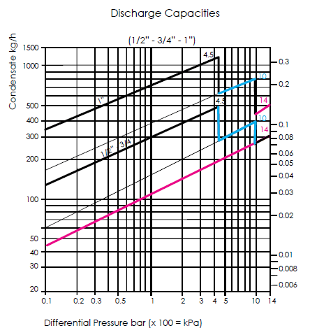 For example, when condensate fills the trap, the denser fluid rests on the bottom of the trap and steam rises to the top. A typical steam trap maintenance program should include at least yearly testing of all steam traps to find leaking traps and replace failed traps. Conversely, steam has a much higher velocity and dynamic pressure, so when steam approaches the trap, the decrease in static pressure and increase in velocity creates a pressure drop to close the valve, according to an article in Chemical Processing written by Tracy Q. and half the diameter for piping above 4 in., but never less than 4 in. Condensate is a low-velocity fluid causing an increase in static pressure that lifts the valve and allows the condensate to be removed from the trap. Any cookies that may not be particularly necessary for the website to function and is used specifically to collect user personal data via analytics, ads, other embedded contents are termed as non-necessary cookies. Many times steam system surveys are not implemented due to the cost or staffing required, but the energy savings observed as a result of a properly implemented program will typically pay back the cost to implement the program in less than one year. In short, this means that in order to design a trap with sufficient capacity, the appropriate orifice size and float diameter must be determined. This is why there are multiple options for traps.
  There are conditions when lifting condensate is acceptable, but it should be avoided wherever possible to reduce backpressure on the traps. PDF
  Oversizing steam traps can be equally as problematic as oversizing traps can cool the condensate prior to discharge. Therefore, we must also select the steam trap orifice to be able to operate at that maximum pressure. We determined the maximum steam pressure for our application was a 150 psi. But opting out of some of these cookies may affect your browsing experience. The diameter of an orifice is much smaller than the inner diameter of the connected piping. Noncondensable gases such as oxygen and carbon dioxide produce carbonic acid, scale, and corrosion, creating conditions that promote leaks within the distribution system. With superheated steam, a check valve should be installed at inlet or trap may lose prime. At this point, it is acceptable to return the condensate to the boiler for reuse. Figure 2 shows an example of a drip leg and trap. Again, I said this is the process application and were going to utilize a continuous flow, which is a flow in thermostatic mechanical design steam trap. However, for the trap to operate at the same pressure differential, this would require a proportionally larger float, which would in turn increase the size of the trap body. Data for proper steam trap sizing. Next, we want to determine the inlet pressure to the control valve.
  As the trap fills with condensate, the float will rise, actuate the valve, and discharge the condensate. Example, 100 psi operating steam line does not mean 100 psi at the control valve. This article will provide a holistic approach to steam and condensate systems by discussing the various types of steam traps, recommended locations for them, basic trap sizing, general steam and condensate design guidelines, and the various methods for testing steam traps to reduce wasted energy and dollars. 0000004211 00000 n
The sizing factor for: The float and thermostatic: Two to one. Any time we modulate steam, we want the condensate line to be zero psi. %PDF-1.3
%
ASME B31.1 includes the design, fabrication, erection, testing, and inspection of high-pressure power piping for systems exceeding 15 psig.
As the trap fills with condensate, the float will rise, actuate the valve, and discharge the condensate. Example, 100 psi operating steam line does not mean 100 psi at the control valve. This article will provide a holistic approach to steam and condensate systems by discussing the various types of steam traps, recommended locations for them, basic trap sizing, general steam and condensate design guidelines, and the various methods for testing steam traps to reduce wasted energy and dollars. 0000004211 00000 n
The sizing factor for: The float and thermostatic: Two to one. Any time we modulate steam, we want the condensate line to be zero psi. %PDF-1.3
%
ASME B31.1 includes the design, fabrication, erection, testing, and inspection of high-pressure power piping for systems exceeding 15 psig. 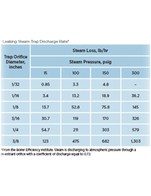 Example would be this here. *QeMRx@R,m@X^AxbJ1 C^l'fyS_l+3Ef\
endstream
endobj
311 0 obj
758
endobj
276 0 obj
<<
/Type /Page
/Parent 267 0 R
/Resources 304 0 R
/Contents 305 0 R
/MediaBox [ 0 0 612 792 ]
/CropBox [ 0 0 612 792 ]
/Rotate 0
/Thumb 191 0 R
>>
endobj
277 0 obj
<<
/Count 13
/Type /Outlines
/First 278 0 R
/Last 279 0 R
>>
endobj
278 0 obj
<<
/Title (.1~,7p )
/Parent 277 0 R
/A 303 0 R
/Next 300 0 R
>>
endobj
279 0 obj
<<
/Title ("5U\nqU)
/Prev 280 0 R
/Parent 277 0 R
/A 281 0 R
>>
endobj
280 0 obj
<<
/Title (u$ p')
/Next 279 0 R
/Prev 282 0 R
/Parent 277 0 R
/A 283 0 R
>>
endobj
281 0 obj
<<
/S /GoTo
/D [ 136 0 R /XYZ 79 794 null ]
>>
endobj
282 0 obj
<<
/Title (CHf7[)
/Next 280 0 R
/Prev 284 0 R
/Parent 277 0 R
/A 285 0 R
>>
endobj
283 0 obj
<<
/S /GoTo
/D [ 130 0 R /XYZ 79 794 null ]
>>
endobj
284 0 obj
<<
/Title (Ri`:QB)
/Next 282 0 R
/Prev 286 0 R
/Parent 277 0 R
/A 287 0 R
>>
endobj
285 0 obj
<<
/S /GoTo
/D [ 43 0 R /XYZ -179 827 null ]
>>
endobj
286 0 obj
<<
/Title (=j"yka;^5/)
/Next 284 0 R
/Prev 288 0 R
/Parent 277 0 R
/A 289 0 R
>>
endobj
287 0 obj
<<
/S /GoTo
/D [ 124 0 R /XYZ 79 794 null ]
>>
endobj
288 0 obj
<<
/Title (xpW\n7J:},y)
/Next 286 0 R
/Prev 290 0 R
/Parent 277 0 R
/A 291 0 R
>>
endobj
289 0 obj
<<
/S /GoTo
/D [ 118 0 R /XYZ 79 794 null ]
>>
endobj
290 0 obj
<<
/Title (q3i[T.b=a)
/Next 288 0 R
/Prev 292 0 R
/Parent 277 0 R
/A 293 0 R
>>
endobj
291 0 obj
<<
/S /GoTo
/D [ 112 0 R /XYZ 79 794 null ]
>>
endobj
292 0 obj
<<
/Title ($Ni*Ru\))
/Next 290 0 R
/Prev 294 0 R
/Parent 277 0 R
/A 295 0 R
>>
endobj
293 0 obj
<<
/S /GoTo
/D [ 81 0 R /XYZ 79 794 null ]
>>
endobj
294 0 obj
<<
/Title ("yu!;4sLs)
/Next 292 0 R
/Prev 296 0 R
/Parent 277 0 R
/A 297 0 R
>>
endobj
295 0 obj
<<
/S /GoTo
/D [ 75 0 R /XYZ 79 794 null ]
>>
endobj
296 0 obj
<<
/Title (b2C11P\rqI)
/Next 294 0 R
/Prev 298 0 R
/Parent 277 0 R
/A 299 0 R
>>
endobj
297 0 obj
<<
/S /GoTo
/D [ 69 0 R /XYZ 79 794 null ]
>>
endobj
298 0 obj
<<
/Title (,[\("7HU$)
/Next 296 0 R
/Prev 300 0 R
/Parent 277 0 R
/A 301 0 R
>>
endobj
299 0 obj
<<
/S /GoTo
/D [ 63 0 R /XYZ -51 794 null ]
>>
endobj
300 0 obj
<<
/Title (T8hy)
/A 302 0 R
/Next 298 0 R
/Prev 278 0 R
/Parent 277 0 R
>>
endobj
301 0 obj
<<
/S /GoTo
/D [ 49 0 R /XYZ 79 794 null ]
>>
endobj
302 0 obj
<<
/S /GoTo
/D [ 49 0 R /XYZ 79 794 null ]
>>
endobj
303 0 obj
<<
/S /GoTo
/D [ 10 0 R /XYZ -51 797 null ]
>>
endobj
304 0 obj
<<
/ProcSet [ /PDF /Text /ImageC ]
/Font << /F2 307 0 R >>
/XObject << /Im1 309 0 R >>
/ExtGState << /GS1 308 0 R >>
>>
endobj
305 0 obj
<< /Length 185 /Filter /FlateDecode >>
stream
Example would be this here. *QeMRx@R,m@X^AxbJ1 C^l'fyS_l+3Ef\
endstream
endobj
311 0 obj
758
endobj
276 0 obj
<<
/Type /Page
/Parent 267 0 R
/Resources 304 0 R
/Contents 305 0 R
/MediaBox [ 0 0 612 792 ]
/CropBox [ 0 0 612 792 ]
/Rotate 0
/Thumb 191 0 R
>>
endobj
277 0 obj
<<
/Count 13
/Type /Outlines
/First 278 0 R
/Last 279 0 R
>>
endobj
278 0 obj
<<
/Title (.1~,7p )
/Parent 277 0 R
/A 303 0 R
/Next 300 0 R
>>
endobj
279 0 obj
<<
/Title ("5U\nqU)
/Prev 280 0 R
/Parent 277 0 R
/A 281 0 R
>>
endobj
280 0 obj
<<
/Title (u$ p')
/Next 279 0 R
/Prev 282 0 R
/Parent 277 0 R
/A 283 0 R
>>
endobj
281 0 obj
<<
/S /GoTo
/D [ 136 0 R /XYZ 79 794 null ]
>>
endobj
282 0 obj
<<
/Title (CHf7[)
/Next 280 0 R
/Prev 284 0 R
/Parent 277 0 R
/A 285 0 R
>>
endobj
283 0 obj
<<
/S /GoTo
/D [ 130 0 R /XYZ 79 794 null ]
>>
endobj
284 0 obj
<<
/Title (Ri`:QB)
/Next 282 0 R
/Prev 286 0 R
/Parent 277 0 R
/A 287 0 R
>>
endobj
285 0 obj
<<
/S /GoTo
/D [ 43 0 R /XYZ -179 827 null ]
>>
endobj
286 0 obj
<<
/Title (=j"yka;^5/)
/Next 284 0 R
/Prev 288 0 R
/Parent 277 0 R
/A 289 0 R
>>
endobj
287 0 obj
<<
/S /GoTo
/D [ 124 0 R /XYZ 79 794 null ]
>>
endobj
288 0 obj
<<
/Title (xpW\n7J:},y)
/Next 286 0 R
/Prev 290 0 R
/Parent 277 0 R
/A 291 0 R
>>
endobj
289 0 obj
<<
/S /GoTo
/D [ 118 0 R /XYZ 79 794 null ]
>>
endobj
290 0 obj
<<
/Title (q3i[T.b=a)
/Next 288 0 R
/Prev 292 0 R
/Parent 277 0 R
/A 293 0 R
>>
endobj
291 0 obj
<<
/S /GoTo
/D [ 112 0 R /XYZ 79 794 null ]
>>
endobj
292 0 obj
<<
/Title ($Ni*Ru\))
/Next 290 0 R
/Prev 294 0 R
/Parent 277 0 R
/A 295 0 R
>>
endobj
293 0 obj
<<
/S /GoTo
/D [ 81 0 R /XYZ 79 794 null ]
>>
endobj
294 0 obj
<<
/Title ("yu!;4sLs)
/Next 292 0 R
/Prev 296 0 R
/Parent 277 0 R
/A 297 0 R
>>
endobj
295 0 obj
<<
/S /GoTo
/D [ 75 0 R /XYZ 79 794 null ]
>>
endobj
296 0 obj
<<
/Title (b2C11P\rqI)
/Next 294 0 R
/Prev 298 0 R
/Parent 277 0 R
/A 299 0 R
>>
endobj
297 0 obj
<<
/S /GoTo
/D [ 69 0 R /XYZ 79 794 null ]
>>
endobj
298 0 obj
<<
/Title (,[\("7HU$)
/Next 296 0 R
/Prev 300 0 R
/Parent 277 0 R
/A 301 0 R
>>
endobj
299 0 obj
<<
/S /GoTo
/D [ 63 0 R /XYZ -51 794 null ]
>>
endobj
300 0 obj
<<
/Title (T8hy)
/A 302 0 R
/Next 298 0 R
/Prev 278 0 R
/Parent 277 0 R
>>
endobj
301 0 obj
<<
/S /GoTo
/D [ 49 0 R /XYZ 79 794 null ]
>>
endobj
302 0 obj
<<
/S /GoTo
/D [ 49 0 R /XYZ 79 794 null ]
>>
endobj
303 0 obj
<<
/S /GoTo
/D [ 10 0 R /XYZ -51 797 null ]
>>
endobj
304 0 obj
<<
/ProcSet [ /PDF /Text /ImageC ]
/Font << /F2 307 0 R >>
/XObject << /Im1 309 0 R >>
/ExtGState << /GS1 308 0 R >>
>>
endobj
305 0 obj
<< /Length 185 /Filter /FlateDecode >>
stream
By submitting this form, you consent to receiving marketing communications from Inveno Engineering. The sizing factor for: Inverted buckets: Three to One. This test-and-replace strategy is subject to two main costs by the owner: testing and steam loss. Table 1provides the recommended steam trap to use based on the location and function within typical heating and process systems. The most common type of thermodynamic trap is a disc type where the disc is the only moving part. Air limits piping systems ability to carry their full capacity of steam and acts as an insulating agent within heat transfer devices. All working components can be replaced with the trap body remaining in-line. A failed oversized trap has a larger orifice opening that can potentially blow through larger quantities of steam and waste more energy. The worst-case scenario would assume the entire orifice is open, but typically condensate simultaneously flows through the trap so approximately 1/3 to 1/2 of the orifice will contain lost steam, according to the DOE. This bypassed steam provides no useful heating value to the system and effectively reduces the overall capacity of the system or requires additional capacity to make up for the system losses to meet the demand of the building. 0000002549 00000 n
0000006695 00000 n
., The GP14 Power Trap (photo) is an advanced condensate-recovery system for pumping high-temperature condensate for vented receivers, sumps and other, Testing steam-trap stations can be very easy if the plant provides the correct equipment, training and commitment to the steam-system, Steam often provides the majority of heat, but its quality is not always carefully managed. The other one for mechanical, is the inverted buckets and it works the same way as we were talking about the other application was flow and thermostatic and you have a differential pressure up here of 50 psi, you would go down to the chart, til you find something 2000 pounds per hour and make your selection of the orifices that are there. Steam traps in HVAC applications are generally found in two locations: drip traps and at process equipment. We have a 50-psi differential across a steam trap. This pulls the disc off the seat allowing condensate to be discharged through the seat orifice located at the top of the trap. Piping in condensate systems is recommended to be schedule 80 steel piping in most cases, due to heavier wall thicknesses to extend the life of the pipe. The operating pressure to the process as you can see is at 75 psi. The PDF document will be sent to the email address specified. Failed steam traps can have a spiraling cost impact above and beyond wasted steam, including increased feedwater costs, additional chemical treatment and make-up water, and higher blowdown requirements. 0000003351 00000 n
s%zD%*ll7wUX)
(Ca
[Bm],f:W. Implement a Sustainable Steam Trap Management Program, Impact Plant Performance by Improving the Steam System, Water Hammer: In Steam Distribution Lines, Water Hammer: In Condensate Transport Piping, Identifying Water Hammer Using a Thermal Camera, Mitigation of Water Hammer in Vertical Flashing Condensate Transport Piping. Steam Trap Management: Do Something; Anything. Examples of thermostatic steam traps include bi-metal and bellows type steam traps. Here are some tips on, The new IBV range of high-pressure inverted-bucket steam traps (photo) are available in sizes from to 3 in. of Energy (DOE), approximately 20% of steam leaving a boiler plant could be lost due to leaking steam traps in steam systems without a preventative maintenance program. Test methods to determine steam trap operation can be segmented into four categories: visual, ultrasonic, temperature, and conductivity. At the inlet to the steam trap, a strainer with a blowdown valve will provide the ability to remove any scale, dirt, and debris in the piping system and allow an operator to depressurize the steam trap for maintenance. To get the most accurate diagnosis, maintenance personnel should integrate conductivity readings with temperature. Going back to our example, again, is that we have 75 psi to the inlet of this valve, it doesnt mean we have 75 psi down here. Now, we determine the orifice size for the following data required. Print All rights reserved. Intentional back pressure is the design of the system and a lot of systems we will run under pressure. Check Valve (suffix CV) Built-in Inlet Check Valve is recommended when used on Superheated Steam
By David Grassl, PE, Ring & DuChateau LLP, Milwaukee, By using this website, you agree to our use of cookies. When steam enters, it fills the inverted bucket causing the bucket to float to the surface which closes the discharge valve, containing the steam in
0000006886 00000 n
Steam traps should generally be sized two to three times the amount of condensate that will be produced under normal operation to account for varying pressures and condensate loads. 0000003839 00000 n
Drip traps consist of a short piece of vertical pipe called a drip leg on the bottom of the steam main with a steam trap. Flash steam is created when condensate flashes to vapor upon expansion to atmospheric pressure and is typically a billowing plume, compared to live steam which is a sharper, higher velocity plume that may not be immediately visible as it exits the test valve, according to the DOE. Many factors influence the success of a steam and condensate system. Devices on the market today are able to compare the sound of a known condition to the tested trap to accurately determine if the trap is functional or blowing steam. Size/Model: IB1031, 80 PSIG, Specify pipe size (1/2, 3/4), or IB1041, 80 PSIG, Specify pipe size (3/4, 1), How to Order Accessories:
Learn to estimate the amounts of energy and money wasted from a blown steam trap. 272 0 obj
<<
/Linearized 1
/O 276
/H [ 1494 881 ]
/L 1148579
/E 17121
/N 35
/T 1143020
>>
endobj
xref
272 40
0000000016 00000 n
Comment Visual indication requires that the personnel observing the visual cues be knowledgeable enough to determine the condition of the steam trap as blow-through steam and flash steam can both escape the test connection with only one indicating a failure. Drip traps are located as part of the main steam distribution piping as the system radiates heat, loses energy, and creates condensate within the piping system. Visual: Visual testing involves a test valve arrangement or inline sight glass to visually determine if the steam trap is malfunctioning. At the bottom of the drip leg, a drain valve should be provided to remove condensate, and isolation valves and unions are recommended at the inlet and outlet of the steam trap to simplify trap removal. For example, the orifice diameters available for the J3X Free Float steam trap are only approx. Snow. Certain articles contain the author's personal recommendations only. Example would be a two-inch steam trap can have the same condensate capacity as a 1/2-inch steam trap, what we need to determine is the condensate capacity and orifice size inside the steam trap. per 10 ft to ensure adequate condensate removal. Click here to start this process. trailer
<<
/Size 312
/Info 265 0 R
/Encrypt 274 0 R
/Root 273 0 R
/Prev 1143009
/ID[<4f7aff5ea1b7af363ec59855866f3c9f><4f7aff5ea1b7af363ec59855866f3c9f>]
>>
startxref
0
%%EOF
273 0 obj
<<
/Type /Catalog
/Pages 264 0 R
/Outlines 277 0 R
/PageMode /UseOutlines
/OpenAction 275 0 R
>>
endobj
274 0 obj
<<
/Filter /Standard
/V 1
/R 2
/O ( UV.`Dz-#_m_}g)
/U (.&eSL+4Pec_$].s)
/P -12
>>
endobj
275 0 obj
<<
/S /GoTo
/D [ 276 0 R /FitH -32768 ]
>>
endobj
310 0 obj
<< /S 656 /T 840 /O 926 /Filter /FlateDecode /Length 311 0 R >>
stream
What does that mean? I must go back to my chart and continue down to see something greater than 2000 pounds per hour, with an orifice rated for 150 psi or higher. Therefore, we end up with 50 psi on the inlet of the steam trap or what we call P4. Mechanical traps discharge condensate at the same temperature as steam, which makes them great for areas of high heat transfer at equipment such as heating coils or heat exchangers. 0000002929 00000 n
The, Scrolling or Pushing? Eventually, the steam is bled off through a small hole in the top of the bucket causing it to sink, which repeats the cycle. What were looking to do is size the internal discharge orifice inside the steam trap. 0000004572 00000 n
We have found out what P4 is and we calculated for this example, lets say a 1000 pounds per hour condensate capacity. Necessary cookies are absolutely essential for the website to function properly. To get closer to the capacity, actual capacity of the steam trap, I might use a little bit higher pressure orifice, which gives me a little bit lower of a capacity and closer to the 2000 pounds Im looking at. We want to know the maximum steam pressure for the steam trap body rating and the maximum steam temperature. We have our differential pressure. When ordering replacement lever and seat assemblies, specify model and operating pressure. As steam pressures, temperatures, and flow rates constantly vary, selection of the appropriate steam trap becomes more complicated. At the takeoff, include a drip leg and trap as described above in addition to the heat transfer equipment steam trap (see Figure 3). The recommended vertical length of the drip leg should be 28 in. Example: IB1031-12-N-125-TV, Thermic Vent & Check Valve (suffix TCV) For combination of Check Valve & Thermic Vent
A replacement kit containing the lever and seat assembly is a more economical option than replacing the entire steam trap. Taking a look at the above data sheet (for J3X Free Float steam trap), it can be seen that different connection piping sizes (i.e. Good system design coupled with the understanding of a correctly sized steam trap for the duty is a critical first step. All steam traps should be located below the device they serve to allow condensate to be removed by gravity and not rely on pressure or velocity. We have, lets say a 15 psi drop across a valve and then we come into the heat transfer and then well have a 10 psi drop across the heat exchange. Condensate should also be drained into the top of the main condensate header similar to steam takeoffs to prevent hot condensate from mixing with cool condensate, causing flash steam and water hammer, according to the article by Paffel. Grassl has designed various high- and low-pressure steam systems including steam-to-hot-water heat exchangers, steam humidifiers, steam heating coils, and kitchen equipment. Maximum condensate capacity in pounds per hour and minimum condensate capacity in pounds per hour. This is because although piping is generally sized for two-phase flow (condensate with steam vapor), the orifice only needs to be sized for the condensate volume. Testing valves provide a visual observation of the fluid downstream of the steam trap by allowing a momentary discharge of the downstream fluid. In the case of most mechanical type traps, it is the size of the orifice, not the size of the connection port, that determines the discharge capacity. Because proper steam piping design impacts condensate removal, steam takeoff to the process equipment should be a top takeoff to provide the highest quality dry steam in the distribution system, which reduces condensate from the bottom of the distribution main from getting into the equipment. The information can be obtained from the heat transfer performance sheets. These traps should be located at the end of mains; bottom of risers; ahead of pressure regulating valves, controls valves, and isolation valves; at pipe bends; and near expansion joints to allow the collection of condensate. inch, inch and 1 inch) all have the same discharge capacity for a given orifice size. After condensing the steam, the best method to improve steam system efficiency is to return the maximum quantity of condensate to the boiler plant for reuse in the production of steam. Steam System Optimization and Risk Mitigation, Risk Based Methodology for Industrial Steam Systems, Why Bad Things Happen to Good Steam Equipment, Steam System Winterization: How to Protect Your Plant, Wet Steam vs. Dry Steam: The Importance of the Steam Dryness Fraction, Separators and their Role in the Steam System, Best Practices for Condensate Removal on Steam Lines, Installation Tips for Steam Traps on Steam Mains, Allocate New Plant Focus to Steam System DesignPart 1, Returning Condensate and When to Use Condensate Pumps, Condensate Recovery: Vented vs. Pressurized Systems, Steam Heat Exchangers are Underworked and Over-Surfaced, Allocate New Plant Focus to Steam System DesignPart 2, Optimize Reboiler Performance via Effective Condensate Drainage, Vent Away Condensate Pump Frustrations in a Flash, Management Strategies for Conserving Energy, Improving Compressed Air Quality and Countermeasures Against Leaks, Free Float Steam Traps for Steam Mains and Tracer Lines. Understand the variety of steam trap options and when to use each one. David Grassl is a mechanical engineer at Ring & DuChateau, and an adjunct professor in the civil and architectural engineering and construction management department at the Milwaukee School of Engineering. For example, when condensate fills the trap, the denser fluid rests on the bottom of the trap and steam rises to the top. A typical steam trap maintenance program should include at least yearly testing of all steam traps to find leaking traps and replace failed traps. Conversely, steam has a much higher velocity and dynamic pressure, so when steam approaches the trap, the decrease in static pressure and increase in velocity creates a pressure drop to close the valve, according to an article in Chemical Processing written by Tracy Q. and half the diameter for piping above 4 in., but never less than 4 in. Condensate is a low-velocity fluid causing an increase in static pressure that lifts the valve and allows the condensate to be removed from the trap. Any cookies that may not be particularly necessary for the website to function and is used specifically to collect user personal data via analytics, ads, other embedded contents are termed as non-necessary cookies. Many times steam system surveys are not implemented due to the cost or staffing required, but the energy savings observed as a result of a properly implemented program will typically pay back the cost to implement the program in less than one year. In short, this means that in order to design a trap with sufficient capacity, the appropriate orifice size and float diameter must be determined. This is why there are multiple options for traps. There are conditions when lifting condensate is acceptable, but it should be avoided wherever possible to reduce backpressure on the traps. PDF Oversizing steam traps can be equally as problematic as oversizing traps can cool the condensate prior to discharge. Therefore, we must also select the steam trap orifice to be able to operate at that maximum pressure. We determined the maximum steam pressure for our application was a 150 psi. But opting out of some of these cookies may affect your browsing experience. The diameter of an orifice is much smaller than the inner diameter of the connected piping. Noncondensable gases such as oxygen and carbon dioxide produce carbonic acid, scale, and corrosion, creating conditions that promote leaks within the distribution system. With superheated steam, a check valve should be installed at inlet or trap may lose prime. At this point, it is acceptable to return the condensate to the boiler for reuse. Figure 2 shows an example of a drip leg and trap. Again, I said this is the process application and were going to utilize a continuous flow, which is a flow in thermostatic mechanical design steam trap. However, for the trap to operate at the same pressure differential, this would require a proportionally larger float, which would in turn increase the size of the trap body. Data for proper steam trap sizing. Next, we want to determine the inlet pressure to the control valve. As the trap fills with condensate, the float will rise, actuate the valve, and discharge the condensate. Example, 100 psi operating steam line does not mean 100 psi at the control valve. This article will provide a holistic approach to steam and condensate systems by discussing the various types of steam traps, recommended locations for them, basic trap sizing, general steam and condensate design guidelines, and the various methods for testing steam traps to reduce wasted energy and dollars. 0000004211 00000 n
The sizing factor for: The float and thermostatic: Two to one. Any time we modulate steam, we want the condensate line to be zero psi. %PDF-1.3
%
ASME B31.1 includes the design, fabrication, erection, testing, and inspection of high-pressure power piping for systems exceeding 15 psig. Example would be this here. *QeMRx@R,m@X^AxbJ1 C^l'fyS_l+3Ef\
endstream
endobj
311 0 obj
758
endobj
276 0 obj
<<
/Type /Page
/Parent 267 0 R
/Resources 304 0 R
/Contents 305 0 R
/MediaBox [ 0 0 612 792 ]
/CropBox [ 0 0 612 792 ]
/Rotate 0
/Thumb 191 0 R
>>
endobj
277 0 obj
<<
/Count 13
/Type /Outlines
/First 278 0 R
/Last 279 0 R
>>
endobj
278 0 obj
<<
/Title (.1~,7p )
/Parent 277 0 R
/A 303 0 R
/Next 300 0 R
>>
endobj
279 0 obj
<<
/Title ("5U\nqU)
/Prev 280 0 R
/Parent 277 0 R
/A 281 0 R
>>
endobj
280 0 obj
<<
/Title (u$ p')
/Next 279 0 R
/Prev 282 0 R
/Parent 277 0 R
/A 283 0 R
>>
endobj
281 0 obj
<<
/S /GoTo
/D [ 136 0 R /XYZ 79 794 null ]
>>
endobj
282 0 obj
<<
/Title (CHf7[)
/Next 280 0 R
/Prev 284 0 R
/Parent 277 0 R
/A 285 0 R
>>
endobj
283 0 obj
<<
/S /GoTo
/D [ 130 0 R /XYZ 79 794 null ]
>>
endobj
284 0 obj
<<
/Title (Ri`:QB)
/Next 282 0 R
/Prev 286 0 R
/Parent 277 0 R
/A 287 0 R
>>
endobj
285 0 obj
<<
/S /GoTo
/D [ 43 0 R /XYZ -179 827 null ]
>>
endobj
286 0 obj
<<
/Title (=j"yka;^5/)
/Next 284 0 R
/Prev 288 0 R
/Parent 277 0 R
/A 289 0 R
>>
endobj
287 0 obj
<<
/S /GoTo
/D [ 124 0 R /XYZ 79 794 null ]
>>
endobj
288 0 obj
<<
/Title (xpW\n7J:},y)
/Next 286 0 R
/Prev 290 0 R
/Parent 277 0 R
/A 291 0 R
>>
endobj
289 0 obj
<<
/S /GoTo
/D [ 118 0 R /XYZ 79 794 null ]
>>
endobj
290 0 obj
<<
/Title (q3i[T.b=a)
/Next 288 0 R
/Prev 292 0 R
/Parent 277 0 R
/A 293 0 R
>>
endobj
291 0 obj
<<
/S /GoTo
/D [ 112 0 R /XYZ 79 794 null ]
>>
endobj
292 0 obj
<<
/Title ($Ni*Ru\))
/Next 290 0 R
/Prev 294 0 R
/Parent 277 0 R
/A 295 0 R
>>
endobj
293 0 obj
<<
/S /GoTo
/D [ 81 0 R /XYZ 79 794 null ]
>>
endobj
294 0 obj
<<
/Title ("yu!;4sLs)
/Next 292 0 R
/Prev 296 0 R
/Parent 277 0 R
/A 297 0 R
>>
endobj
295 0 obj
<<
/S /GoTo
/D [ 75 0 R /XYZ 79 794 null ]
>>
endobj
296 0 obj
<<
/Title (b2C11P\rqI)
/Next 294 0 R
/Prev 298 0 R
/Parent 277 0 R
/A 299 0 R
>>
endobj
297 0 obj
<<
/S /GoTo
/D [ 69 0 R /XYZ 79 794 null ]
>>
endobj
298 0 obj
<<
/Title (,[\("7HU$)
/Next 296 0 R
/Prev 300 0 R
/Parent 277 0 R
/A 301 0 R
>>
endobj
299 0 obj
<<
/S /GoTo
/D [ 63 0 R /XYZ -51 794 null ]
>>
endobj
300 0 obj
<<
/Title (T8hy)
/A 302 0 R
/Next 298 0 R
/Prev 278 0 R
/Parent 277 0 R
>>
endobj
301 0 obj
<<
/S /GoTo
/D [ 49 0 R /XYZ 79 794 null ]
>>
endobj
302 0 obj
<<
/S /GoTo
/D [ 49 0 R /XYZ 79 794 null ]
>>
endobj
303 0 obj
<<
/S /GoTo
/D [ 10 0 R /XYZ -51 797 null ]
>>
endobj
304 0 obj
<<
/ProcSet [ /PDF /Text /ImageC ]
/Font << /F2 307 0 R >>
/XObject << /Im1 309 0 R >>
/ExtGState << /GS1 308 0 R >>
>>
endobj
305 0 obj
<< /Length 185 /Filter /FlateDecode >>
stream